3
The MINI-STOP will become dangerous when the protective conductor inside or outside the drive will be broken, as
well as with broken protective conductor with protective system.
Any intentional breaking thereof is forbidden.
The connecting conductors should comply with the power load and the min. HO5VV version. The conductor cross-section
should be at least 1 mm
2
, The length thereof should not exceed 5 m. The voltage on the protective conductor should not exceed
3,3 V with the 10 A current.
Caution!
The voltage in the mains must be in conformity with the voltage indicated on the drive plate.
Caution!
The transformer of the bulb for the sewing area is not switched off by the main switch (EN 60204-3-1). Before
proceeding to any repair operation in the transformer box (such as a fuse exchange) the plug categorically must be
taken out of the socket. Such operations may be carried out only by persons with adequate electrotechnical skill.
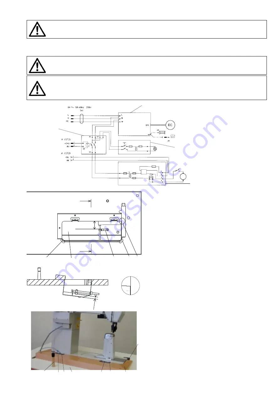
4.3 Assembly of a table top on a stand frame,
assembly of oil tank
- Turn the table top around and screw it down to the frame by
means of screw
ø
8 x 35 mm.
When applying a frame different from that recommended by
the producer, be sure to adapt its position so as to ensure
the stability of the machine head in its tilted state.
- Screw on the microswitch (which is a component part of the
interconnecting cable) on the oil tank (1).
- Oil tank (1) with assembled lever (2) insert through the bot-
tom part into the cut hole in the table top and put down as
shown in detail (D) in that way, that the edge of the tank
would fit in with the edge of the cut hole in the table top. Set
the height of the tank according to the section A-A. Tank
may not protrude out of upper surface of a table top. Nail
down the tank with nails
ø
2 x 40 mm.
- Adjust the lever (2) to the dimensions B and C.
- Stick rubber inserts (3) into the cut-out of the table top.
4.4 Assembly of machine head onto a stand
- Stick down rubber inlays (2) with glue into the groove in a
wedge (1) and put the wedge down on the table top (3).
- Disassemble trasported tank (cover) from the machine head
and assemble hangers (4) on the head.
- Put the head down into the rubber inlays (2) and (5).
- Screw the wedge down to the table top with screws
ø
5 x
30 mm.
- Screw on hinges, using wood screw
ø
5 x 40 mm and screw
M5 (the hinge above the motor), to the table top. Tighten the
wood screw and the screw in such a way, so that the oscilla-
tion of the head on rubber inserts is not limited.
- Insert supporting pin (6).
Circuit layout
1
2
4
3
4
6
2
5
4
5
6
3
A - A
D
B
= ~82
A
A
3
3
D
1
2
C
= 9mm
Summary of Contents for 4182i-1
Page 11: ......


