DURAVANT QC Conveyors AS40 Installation Operation & Maintenance Download Page 14

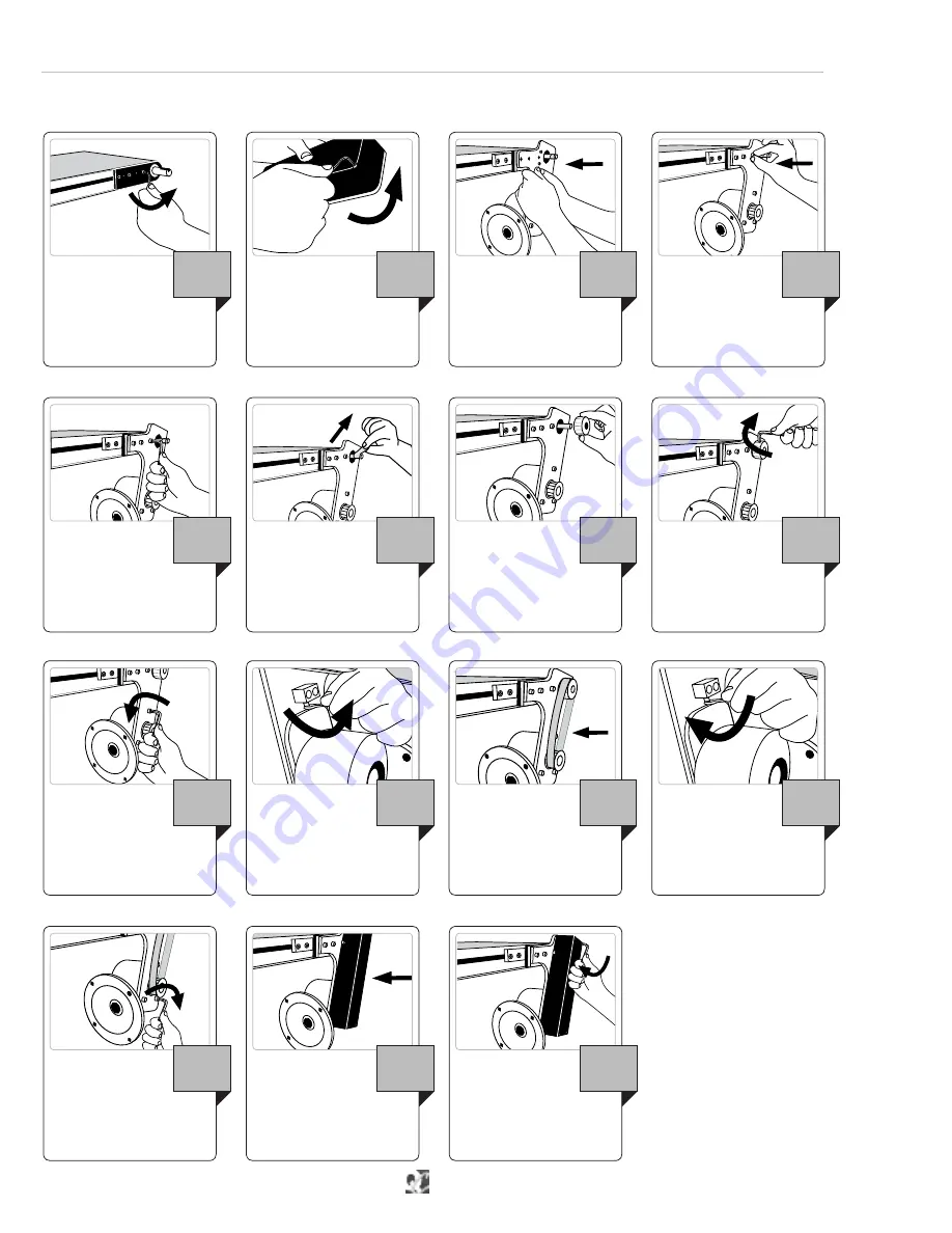
Run square head screw out, 
moving speed reducer away 
from conveyor and creating tension 
on belt.

12

14 | Heavy Duty Top & Bottom Drive Mounting Packages — Drive Packages


  AS40 Manual

Heavy Duty Top & Bottom Drive Mounting Packages

CARET-LEFT

DRIVE PACKAGES

Remove and discard three 
socket head cap screws 
from drive side bearing plate.  
(Do not remove bearing plate)

1

Loosen three socket head 
cap screws holding speed 
reducer in position.

3

x

9

Tighten three socket  
head screws.

5

Retighten three socket head 
cap screws.

3

x

13

Replace guard.

14

Insert and tighten four 
socket head cap screws.

4

x

15

Remove four socket head 
cap screws from guard and 
remove guard.

4

x

2

Tighten jacking screw so 
speed reducer can move 
toward conveyor.

10

Remove nylon tape holding 
key in place.  
(Do not remove key)

6

Mount drive package over 
drive mounting plate.

3

Install timing belt  
over sprockets.

11

Slide top sprocket onto 
conveyor‘s output shaft 
and key.

7

Align mounting holes  
and install three socket 
head screws.

3

x

4

Tighten set screws to secure 
in place.

8

The Drive Package will ship separate from the conveyor. For Heavy Duty Drives, the motor is always shipped in its own box; the right angle 
speed reducer will be attached to the drive mounting package.

3

x

3

x

2

x

Summary of Contents for QC Conveyors AS40

Page 1: ...4057 Clough Woods Drive Batavia OH 45103 USA 1 513 753 6000 qcconveyors com CONTENTS Recommended Spare Parts 2 Warnings 3 Tools 3 Installation 4 Drive Packages 11 Maintenance 16 Troubleshooting 22 Exp...

Page 2: ...EFT Conveyor Spare Parts Drawing Page Tail Assembly 28 White Urethane Belt 24 25 Drive End Bearing Housing 26 27 Full Width Underside Idler 31 Stub Roller Underside Idlers 29 30 Pulley Assembly 26 CON...

Page 3: ...WARNINGS When used improperly the con veyor rollers can pinch or maim Lock out power before servicing the conveyor Do not use with the guards removed Read this manual before operating Exposed moving p...

Page 4: ...king slip and inform QC Conveyors of any discrepancies If you need assistance please contact QC Conveyors customer service department Monday through Friday 8am 5pm EST at 513 753 6000 In addition your...

Page 5: ...rs6 wideorless flange shouldpointoutward spacermustbe installedbetweenstandattachment bracketandconveyorframe For conveyors more than 6 wide flange should point inward no spacer is necessary 3 Place s...

Page 6: ...nt plate 4 x 6 Ensuring the socket head cap screw is facing you slide Quick Clamp into tee slot at desired mounting position 4 Loosen two lower screws in each stand bracket using a 5mm allen wrench 1...

Page 7: ...socket head cap screws through angle brace and into drop in nut in the conveyor frame 6 Tighten socket head cap screw on frame 7 Tighten socket head cap screw on stand 8 Check with bubble level to en...

Page 8: ...1 Align mount to drop in nuts 1 Insert socket head cap screws through mount and into drop in nut 2 x 2 Insert socket head cap screws through mount and into drop in nut 2 Tighten screws to secure mount...

Page 9: ...drop in nuts 2 Tighten screws in guide clamps 10 Insert socket head cap screw through guide clamp and into drop in nuts 3 Re tighten screws in tracking block 2 x 11 Insert two drop in nuts into t slot...

Page 10: ...desired height and tighten screw on crossblock to secure Guide should NOT touch belt 13 Loosely thread adjusting rod into nuts 2 Slide guiderail assembly over vertical rods on frame 10 Tighten socket...

Page 11: ...ead cap screws 5 Ensure set screws on couplings are tight Belt may need to be rotated to reveal set screws in window 500 8 Tighten two socket head cap screws 6 Conveyor may tip after motor is installe...

Page 12: ...nting plate 1 Install flat head screws into countersunk holes 3 x 5 Remove and discard three socket head cap screws from drive side bearing plate Do not remove bearing plate 3 Loosen four hex nuts hol...

Page 13: ...ES Run jacking screw out to create tension on belt Approximately 6lbs of force to deflect one span of belt 09 13 Retighten set screws to secure pivot drive in place 17 Retighten four hex nuts 4 x 14 R...

Page 14: ...e guard 14 Insert and tighten four socket head cap screws 4 x 15 Remove four socket head cap screws from guard and remove guard 4 x 2 Tighten jacking screw so speed reducer can move toward conveyor 10...

Page 15: ...n motor 3 Lightly strike just behind the key with a screwdriver and hammer 4 Rotate quill pin on speed reducer so that keyway is in 12 o clock position 7 Install 4 hex head screws 4 x 11 Rotate keyway...

Page 16: ...bly screws on each side of bearing block 6 x 1 Rotate adjustment screw to move tail on side where belt is riding too close 1 Let conveyor make several rotations to ensure belt is tracking properly 3 F...

Page 17: ...ear drive pulley bearing plate 7 Pull belt off of tension release tail 8 Rotate tension release tail assembly up and towards the drive end 2 Loosen screws on mounts brackets on opposite side of drive...

Page 18: ...and into the locked position Frame end could have sharp edges Conveyor is now ready to be tracked See belt tracking section of manual 7 Insert screws through bracket or mount used and into frame s dr...

Page 19: ...increase tension Adjust both screws the same amount 1 Extend the square head tracking screws on both sides of the conveyor until desired tension is achieved extend screws the same amount 2 Retighten s...

Page 20: ...l Belt Care Cleaning CARET LEFT MAINTENANCE Spray proper cleaning solution on a clean rag 2 Cycle conveyor to reveal opposite side of belt 4 Inspect Belt for any fraying or tears and replace if needed...

Page 21: ...ack into frame 7 Install and tighten three set screws on one bearing plate 3 x 8 Loosen but do not remove three screws holding bearing plate on opposite side of pulley 3 x 2 Slide bearing plates out o...

Page 22: ...e belt page 19 Belt is slipping or stops under load conveyor belt 22 Tail Pulley Replacement Maintenance AS40 Manual Tail Pulley Replacement CARET LEFT MAINTENANCE Symptom Corrective Action Possible C...

Page 23: ...Motor is not protected with overload protection and is drawing too much current Install overload protection on motor Motor is Hot thermometer full Accumulation or belt wear Refer to Belt Tracking sect...

Page 24: ...LLL SLIDER BED ALUMINUM EXTRUSION 2 WIDE 1D0013ALLLL SLIDER BED ALUMINUM EXTRUSION 3 WIDE 1D0014ALLLL SLIDER BED ALUMINUM EXTRUSION 4 WIDE 1D0015ALLLL SLIDER BED ALUMINUM EXTRUSION 5 WIDE 1D0016ALLLL...

Page 25: ...SY END DRIVE SINGLE OUTPUT LH 1A0029C00WW ASSY END DRIVE SINGLE OUTPUT RH 1A0031C00WW ASSY END DRIVE DUAL OUTPUT 2 1A0039B00WW ASSY TAIL V GUIDED 3 1A0038A00WW ASSY TENSION RELEASE TAIL 4 1A0071A WW L...

Page 26: ...OUSING RH 4 1D0064B DRIVE BEARING HOUSING LH 5 1D0080A ANCHOR BAR BEARING HOUSING 6 SLHCS M6X100X010 BX SCREW SOCKET LOW HEAD CAP M6x1 0 10MM LG 7 1D0125A BLOCK JACKING LH DRIVE END 8 1D0126A BLOCK JA...

Page 27: ...HOUSING RH 4 1D0064B DRIVE BEARING HOUSING LH 5 1D0080A ANCHOR BAR BEARING HOUSING 6 SLHCS M6X100X010 BX SCREW SOCKET LOW HEAD CAP M6x1 0 10MM LG 7 1D0125A BLOCK JACKING LH DRIVE END 8 1D0126A BLOCK J...

Page 28: ...A ASSY ANCHOR BAR TIE SPRING DOWEL PIN 5 1D0164A TAIL BUTTON 6 1D0165A BUTTON RETAINING PLATE 7 1D0168A BUSHING 8 1D0225A BUTTON HEAD SHOULDER SCREW 9 SHSS M06X100X006 ZP SCREW SOCKET HEAD SET M6x1 0...

Page 29: ...5 1 2 3 Part Description 1A0040A 2 6 WIDE STUB UNDERSIDE IDLER ASSEMBLY 1 1D0152A SHAFT STUB UNDERSIDE IDLER 2 6 2 43 0050 51 BEARING UNDERSIDE IDLER STUB 3 43 0050 52 RETAINING RING 4 1D0151A CLAMP...

Page 30: ...BEARING UNDERSIDE IDLER STUB 3 1D0315A RETAINING RING 4 1D0151A CLAMP UNDERSIDE IDLER STUB 5 1D0149A GUARD UNDERSIDE IDLER STUB 8 24 6 PHCS M05X080X016 ZP ST SCREW PAN HEAD TORX M5 X 80 X 16MM 30 Exp...

Page 31: ...WW FULL WIDTH UNDERSIDE IDLER ASSEMBLY FULL ASSEMBLY 1 1A0033A00WW ROLLER ASSY FULL WIDTH UNDERSIDE IDLER 2 1DO2O8A CLAMP UNDERSIDE IDLER FULL WIDTH 3 1D0155A00WW GUARD UNDERSIDE IDLER FULL WIDTH 4 1D...

Page 32: ...N Any attempt to repair such items may actually void the manufacturer s warranty Any description of this unit is only to identify it and is not a warranty that the unit fits the description Any warran...

Page 33: ...ds will be the responsibility of the Purchaser The RGA number must be clearly marked on the outside of all packages It must also be on any paperwork packing slips or delivery receipts If there is no R...

Page 34: ...via OH 45103 513 753 6000 qcconveyors com Registration also entitles you to all the benefits of our Conveyor Configurator where you can configure and quote conveyor systems with help from our engineer...

Page 35: ...nveyors com Service Record 35 CARET LEFT CARET LEFT Date Service Performed Date Service Performed CARET LEFT CARET LEFT Date of Installation Date of Installation Serial Number Serial Number SERVICE RE...

Page 36: ...ve Batavia OH 45103 USA 1 513 753 6000 qcconveyors com MAN AS40 2207 SERVICE RECORD Date Service Performed Date Service Performed Serial Number Date of Installation CARET LEFT Serial Number Date of In...

Reviews: