background image

-8-

Install this appliance in compliance with all local building codes.  In the absence of local codes, 

use the latest edition of The National Fuel Gas Code (ANSZ223.1, also known as NFPA54), 

available from:
American National Standards Institute 

25 West 43rd Street, 4th floor 

New York, NY 10036

or

National Fire Protection Association, Inc.  

1 Batterymarch Park 

Quincy, Massachusetts USA 02169-7471
This appliance is designed to burn with very low emissions, so that it requires no outside venting 

(“ventless” or “vent-free” operation).  It can be installed and used in a fireplace with the flue 

damper closed, as long as the room in which it is installed is adequately ventilated (see Section II, 

Air for Ventilation and Combustion).  State and local codes in some areas prohibit the use of vent-

free heaters.  Check the building codes in your jurisdiction before installation.  This appliance also 

may be operated as a vented decorative product by opening the flue damper of the fireplace.
IMPORTANT: Vent-free appliances add moisture to the air.  Although this is beneficial, installing the 

appliance in rooms without enough ventilation may cause mildew to form from too much moisture 

(see Section II, Air for Ventilation and Combustion).

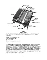
Sliding Burner Cover

Burner Slot

Heat Shield

Fuel Reservoir

Tank Tray

Burner Tube

Piercer

Handle

Fuel Tank Bracket

Grate

Ignition Button

Burner / Base

Screw-down Hole

(Another hole on

opposite side)

Sparker

Figure 1 

Appliance Overview

Summary of Contents for illuma 61000

Page 1: ...installation adjustment alteration service or maintenance can cause injury or property damage Refer to this manual for correct installation and operational procedures WARNING This appliance is for installation only in a solid fuel burning masonry fireplace a UL127 factory built fireplace or in an ANSI Z21 91 ventless firebox It is design certified for these installations in accordance with UL1370 ...

Page 2: ...on 5 III Setup 7 IV Minimum Firebox Dimensions 9 V Installation and Clearances 9 VI Installing Damper Stop 9 VII Installation 9 VIII Installing the Fuel Canister 12 IX Operation 12 X Refueling 14 XI Adjustments 15 XII Maintenance 15 XIII Troubleshooting 17 XIV Parts List 18 Warranty 19 ...

Page 3: ...eas where flammable vapors or gas may be present Never store or transport the fuel in anything other than the original container that it came in Store fuel in a cool and dry place away from heat sources WARNING Risk of indoor air pollution Use this appliance only in well ventilated areas People with breathing problems should consult a physician before using the appliance WARNING Do not use this ap...

Page 4: ...d Heat buildup within the fireplace could cause the glass doors to break or burst or cause the release of harmful combustion products into the living area If the fireplace has vents at the bottom the vents must be opened before running the appliance This appliance is designed to be smokeless If the logs ever begin to smoke extinguish the appliance by pulling on the snuffer device handle underneath...

Page 5: ...s repaired by unqualified persons II AIR FOR VENTILATION AND COMBUSTION WARNING If the area in which the appliance may be operated is smaller than that defined as an unconfined space or if the building is of unusually tight construction provide adequate combustion and ventilation air by one of the methods described in the National Fuel Gas Code ANS Z223 1 Section 5 3 or applicable local codes NOTE...

Page 6: ... air from the outdoors and vent to the outdoors Step 2 Divide the number obtained in Step 1 by 1000 Step 3 Determine the volume of the space length x width x height Add the volume for any other rooms in the space as defined above Step 4 Divide the number obtained in Step 3 by 50 Step 5 Compare the number obtained in Step 4 with the number obtained in Step 2 If the number from Step 4 is smaller the...

Page 7: ...T Do not provide openings for inlet or outlet air into an attic if the attic has a thermostat controlled power vent Heated air entering the attic will activate the powervent III SETUP WARNING This appliance is for use only in a solid fuel burning masonry fireplace a UL127 factory built fireplace or in an approved ventless firebox ANSI Z21 91 CAUTION Do not remove the metal data plate rating plate ...

Page 8: ...h it is installed is adequately ventilated see Section II Air for Ventilation and Combustion State and local codes in some areas prohibit the use of vent free heaters Check the building codes in your jurisdiction before installation This appliance also may be operated as a vented decorative product by opening the flue damper of the fireplace IMPORTANT Vent free appliances add moisture to the air A...

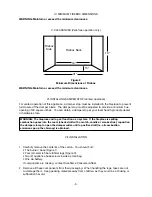
Page 9: ... fireplace is spilling combustion gases into the room check draft with a match candle or smoke stick reposition the damper clamp to open the damper wider until a positive draft i e all combustion emissions go up the chimney is obtained VII INSTALLATION 1 Carefully remove the contents of the carton You should find The burner base Figure 1 Four 4 ceramic fiber artificial logs Figure 3 Two 2 applianc...

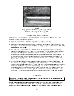
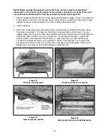
Page 10: ...r and looking into the fuel canister cavity The canister tray should be centered in the opening with the gap between the canister tray and the log wall on the left Figure 6 is equal to the gap on the right Figure 7 Also push the log as far back as possible Then place the left and right small logs on top of the front and rear logs see Figure 8 Ensure that when the door on the front log is opened an...

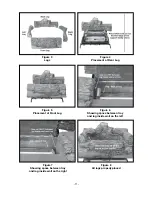
Page 11: ... Rear Log Figure 3 Logs Figure 5 Placement of Front Log Figure 6 Showing space between tray and log inside wall on the left Figure 8 All logs properly placed Figure 7 Showing space between tray and log inside wall on the right ...

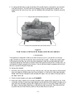
Page 12: ... begins to fill the burner this is normal 4 After the canister has been installed leave it in place and close the door of the front log The appliance is now ready for use At this point the canister still contains fuel and should not be removed until the canister is completely empty The canister automatically feeds more fuel into the burner after the fuel is ignited and starts burning This continue...

Page 13: ...t the front left of the burner base The burner should light If it does not hold down the igniter button until it does You may need to wait a minute or so to allow the duraflame illuma fuel to drain into the burner reservoir Initially the flames might be low with a bluish hue The flames should grow in height and become yellow and orange as the fuel heats up Make sure that your head and face are not...

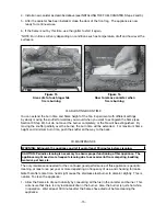
Page 14: ...e the empty canister with a full one This can be done while the appliance is burning there is no need to extinguish the flames To change the canisters 1 Open the door on the top of the front log of the log pile The open door acts as a flame shield Use your fingers to lift the top door as shown in Figure 15 Only touch in the areas indicated Please note that even though the area indicated in Figure ...

Page 15: ...way to the back XII MAINTENANCE WARNING Extinguish the appliance and let it cool at least 30 minutes before cleaning CAUTION Periodic cleaning is necessary to ensure proper functioning of this appliance The appliance might need more frequent cleaning due to excessive lint from carpeting bedding material pet hair etc The only maintenance needed for the continued good performance of this appliance i...

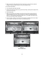
Page 16: ...st the logs gently 7 Make sure that all parts of the appliance are returned to their proper operating positions by following assembly instructions Ensure the logs and the piercer are installed properly see Figure 17 The top surface of the piercer should be level If it is higher on the left end then turn it around and place it back in place again 8 Check for leaks by installing a fuel canister into...

Page 17: ...l DO NOT lift the illuma fuel canister from the tray as this could cause a fuel spill The tubes connecting the burner to the fuel reservoir might be clogged Starting at the tube opening in the bottom of the burner run a thin flexible wire through the length of the tube to remove the obstruction The battery in the igniter may be dead Replace them with new batteries The sparker tip may be out of pos...

Page 18: ... PARTS LIST Part Number 61001 Burner Base 61002 Igniter 61003 Front Log 61004 Back Log 61005 Left Small Log 61006 Right Small Log 61007 Canister Tray Piercer 61008 Heat Shield 61009 Grate 61010 Masonry Screws ...

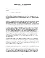
Page 19: ... be obtained through authorized dealers of this product and or Duraflame Inc which will provide original factory replacement parts Failure to use original factory replacement parts voids this warranty Correction in the manner provided above shall constitute a fulfillment of all liabilities of Duraflame Inc with respect to the quality of the product The product MUST be installed by a person capable...

Page 20: ... or limitation of incidental or consequential damages so the above limitation on implied warranties or exclusion or limitation on damages may not apply to you This warranty gives you specific legal rights and you may also have other rights that vary from state to state For information about this warranty write to Attn Consumer Affairs Duraflame Inc 2894 Monte Diablo Ave Stockton CA 95203 www duraf...

Reviews: