Page 26 of 47
Device Info
A custom site name can be entered here, and the model number, serial number, software version, and hardware
version are shown here.
Logging
The SITEGUARD will log all measurements and alarms to an SD card that is plugged into the SITEGUARD board.
Users can set the rate here, as well as clear the card, or append new measurements. The CSV log file can be
downloaded here, as well as the Status page. You can also examine the log file using a terminal connection
through the USB port. If the SD card fills up, the oldest sample is discarded when a new one is stored. The
SITEGUARD custom site name under Device Settings is stored with the logged data, so that the source of the card
can be identified after it removed from the SITEGUARD.
A SITEGUARD connected to a battery backup power system can monitor and log information about AC mains
power outages, as well as all the other measurements for as long as the battery backup lasts. When a log file
reaches 5 MB, it is renamed, and a new one is started.
Download and save all log files to your computer before
clearing the log or data will be permanently lost.
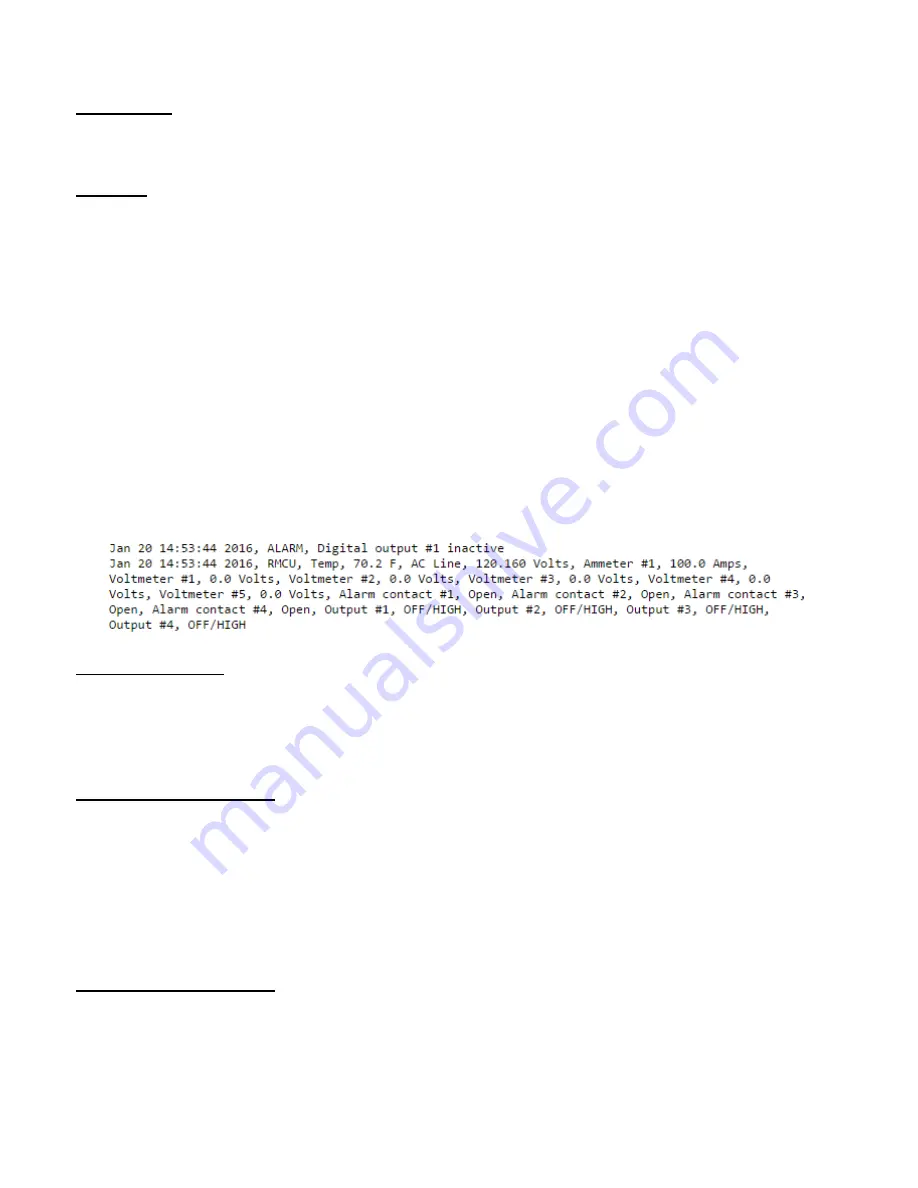
The SITEGUARD has the ability to save log entries when an alarm occurs by choosing “Log Alarms” > “Yes”. You
can log alarms, log periodically by setting the “Logging Rate” minutes, log both, or log none by choosing “Log
Alarms”>”No” and setting the “Logging Rate” to “0”. The Alarm log entry is identified with label entry before the
data entry, as in this example:
Archive graphing
Set the archive graphing sample rate for all analog channels by selecting the sample rate from the dropdown list.
With 1440 samples for each graph you can see the following time spans: 1 Min (1 Day), 2 Min (2 Days), 7 Min (1
Week), 14 Min (2 Weeks), 28 Min (4 Weeks). This does not change the “Live View” mode which samples as fast as
the
Date and Time Settings
Configuration for all date and time settings. Date and time is battery backed up on the card, and the values are
saved in the logged samples. The real-time-clock can synchronize it’s time to the network through an NTP server,
or it can be set manually if a network is not available.
NTP servers can be used by entering
0.north-america.pool.ntp.org,
or another NTP server address
into the
NTP Server box. Your networking firewall must allow access to this server.
An alternate NTP
server can be configured in the second box.
Miscellaneous Settings
The number of significant digits to the right of the decimal point for the analog channels can be configured here.
You can select up to 5 digits to the right of the decimal point.
Temperature can be configured to read in Fahrenheit or Celsius.
Summary of Contents for PSDA-MU1
Page 22: ...Page 22 of 47 NETWORK SETUP...
Page 25: ...Page 25 of 47 DEVICE SETUP...
Page 27: ...Page 27 of 47 SENSOR SETUP...
Page 28: ...Page 28 of 47 Sensor Setup continued DAC and Scheduling...
Page 30: ...Page 30 of 47 ALARM SETUP ANALOG CHANNELS...
Page 31: ...Page 31 of 47 ALARM SETUP TEMPERATURE...
Page 32: ...Page 32 of 47 ALARM SETUP DIGITAL CHANNELS...
Page 33: ...Page 33 of 47 ALARM SETUP SCHEDULING...
Page 36: ...Page 36 of 47 USER SETUP...
Page 39: ...Page 39 of 47 CHARTS SCREEN DEFAULT ARCHIVE DATA...


