110-275
24
Display, Alarm and Error Messages
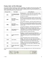
When certain conditions are detected, a message code flashes on the display and the local audio alarm sounds.
Depending on the nature of the condition, power to various systems components, such as the compressor,
heater, fan, and pump, is removed. When the condition is rectified, push the front panel Power Button or turn the
Power Switch OFF then ON to clear the fault or error.
Message Code
Description
Action Required
EFL
Low fluid level warning
—
units with fluid level float
switch
Warning / Alarm
— Fluid level float switch or flow switch is open.
Alarm will sound once every 8 seconds for 5 occurrences. If problem
has not been corrected after 40 seconds, Fault 05 occurs.
Add fluid to the reservoir.
EAF
High ambient
temperature warning
(rear panel)
Warning
- The ambient temperature is higher than the set ambient
limit. The display alternates between EAF and the fluid temperature;
the unit continues normal operation. If this lasts more than 5 seconds,
fault 17 occurs.
Lower ambient temperature or raise high ambient temperature limit.
EHA
High ambient
temperature warning
(front panel)
Warning
— The ambient temperature is higher than the set ambient
limit. The display alternates between EHA and the fluid temperature;
the unit continues normal operation. If this lasts more than 5 seconds,
fault 16 occurs.
Lower ambient temperature or raise high ambient temperature limit.
EHL
High temperature set
point warning
Warning –
The temperature set point is higher than the high
temperature limit value. The display alternates between EHL and the
fluid temperature. The unit continues normal operation. If the fluid
temperature rises above the HL setting, Fault 03 is activated.
Decrease heat load or increase the HL setting.
ELL
Low temperature limit
alarm
Warning
— The temperature set point is lower than the low
temperature limit value. The display alternates between ELL and the
fluid temperature; the unit continues normal operation. If the fluid
temperature stays below the LL value for 25 seconds, Fault 02
occurs.
Increase temperature set point or decrease low limit value.
LLO
Local Lockout
Normal
— Indicates that Local Lockout feature (see
Enabling /
Disabling the Local Lockout
) is enabled. Appears momentarily when
Select/Set Knob is pressed to view/change set point value.
CAn
Cancel Local Lockout
Normal
— Indicates the Local Lockout feature (see
Enabling /
Disabling the Local Lockout
) has been disabled. Appears
momentarily when Local Lockout status is changed from enabled
(LLO) to disabled.
EC
External remote control
active
Normal
— Chiller is in Standby mode until remotely activated
(optional).
If a fault should occur, the left display will show Ft, and the right display will show one of the fault codes shown
below.
Summary of Contents for DCA203C4
Page 1: ...Operator s Manual DuraChill Air and Water Cooled 2 and 3 HP Chillers 110 275 25 February 2015...
Page 9: ...110 275 8 Rear View Power Switch Power Switch...
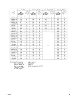
Page 36: ...110 275 35 Pump Performance Specifications subject to change without notice...
Page 40: ...110 275 39 Appendix Flow Diagram Air Cooled Chillers...
Page 41: ...110 275 40 Flow Diagram Water Cooled Chillers...
Page 42: ...110 275 41 Wiring Diagram 208 230V 1 Phase Air Cooled Chillers...
Page 43: ...110 275 42 Wiring Diagram 208 230V 380 460V 3 Phase Air and Water Cooled Chillers...


