110-275
27
Routine Maintenance and Troubleshooting
Routine Maintenance
The Chiller is designed to require a minimum of periodic maintenance.
Condenser, Air Vents and Reusable Filter
To keep the system operating at optimum cooling capacity, the condenser, the air vents, and reusable filter
should be kept free of dust and dirt. They should be checked on a regular basis and cleaned as required.
The reusable filter is easily accessed from either the left or right side of the unit. Use a mild detergent and water
solution to wash off any accumulated dust and dirt. Rinse and dry thoroughly before reinstalling.
Fluid Filter
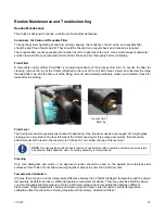
A removable, highly efficient fluid filter is located downstream of the process fluid inlet. To access the filter for
cleaning, remove the top of the Chiller (attached to the rear of the unit with three screws) and unscrew the large
threaded filter cap. Pull the filter out of the fitting, rinse off accumulated particulate matter, and reinstall. Check for
leaks after reinstalling.
Fluid Level
The fluid level should be periodically checked to determine if the fluid level needs to be topped off. A sight glass
viewing port is provided on the rear left side of the Chiller housing for this purpose. Generally, fluid should be
added whenever the level in the reservoir is 2 inches (5.1 cm) below the top of the reservoir.
NOTE:
On units equipped with the heater option, check fluid level when operating at maximum temperature
and allow for fluid expansion. Use of a venting assembly is recommended.
Cleaning
Only mild detergents and water or an approved cleaner should be used on the painted and stainless steel
surfaces of the Chiller. Do not allow cleaning liquids or sprays to enter the Controller vents.
Temperature Calibration
At times, there may be a minor temperature difference between the Chiller’s displayed temperature and the actual
temperature as determined by a certified temperature measurement device. There may also be situations where
you want the displayed temperature to match a particular value to have standardization between different
instruments. These adjustments can be performed using the Chiller’s internal and/or external temperature
calibration offset functions. See “
Setting Operational Parameters, Calibration Offset
”.
Process fluid
filter cap
Summary of Contents for DCA203C4
Page 1: ...Operator s Manual DuraChill Air and Water Cooled 2 and 3 HP Chillers 110 275 25 February 2015...
Page 9: ...110 275 8 Rear View Power Switch Power Switch...
Page 36: ...110 275 35 Pump Performance Specifications subject to change without notice...
Page 40: ...110 275 39 Appendix Flow Diagram Air Cooled Chillers...
Page 41: ...110 275 40 Flow Diagram Water Cooled Chillers...
Page 42: ...110 275 41 Wiring Diagram 208 230V 1 Phase Air Cooled Chillers...
Page 43: ...110 275 42 Wiring Diagram 208 230V 380 460V 3 Phase Air and Water Cooled Chillers...


