4
4 Locating the Power Center Hub
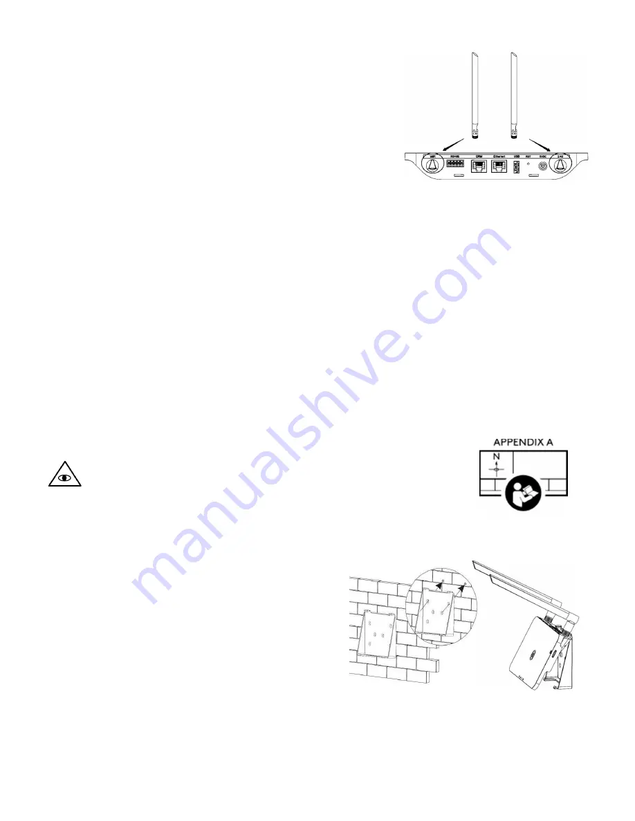
4.1 Installing the antennas
1.
Screw the antennas to the Wi-Fi ports on the rear of the unit.
2.
Adjust the antennas approximately 90 degrees to the base of
the unit.
4.2 Proximity to the PV array
Locating the POWER CENTER HUB as close as physically possible to the PV array is highly recommended to
ensure a strong Wi-Fi signal to the microinverters. For flush mount rooftop PV arrays on wood roof
construction, the unit should be installed on the floor nearest the roof and central to the array.
Roof construction types that include concrete forms and/or standing seam metal may create signal
interference. For these roof types, locating the unit temporarily to establish the strongest signal is
recommended prior to a permanent installation. An outdoor location near to the roof may be required
(enclosure not included). Additional gateways can be installed to pickup undetected microinverter IDs.
4.3 Proximity to the customer supplied internet router
The POWER CENTER HUB can communicate with the router via hard-wired ethernet or Wi-Fi. The ideal
location for microinverter communication may conflict with router communication. In the case that the
resulting Wi-Fi signal between the router and the gateway is weak, there are three options:
1.
Relocate the customer router.
2.
Hardwire the gateway to the customer router via an ethernet cable (not included).
3.
Install a 3
rd
party Wi-Fi bridge/repeater between the gateway and the router.
4.4 Mapping the Power Center Hub to the PV array
NOTE
: The following instruction requires the microinverter serial number
map created during the microinverter installation process.
1.
Remove the s/n label (section 3.2, item - P)from the back of the unit and
paste it to the same sheet used to map the microinverters.
5 Wall mounting option
It is recommended to mount the unit permanently to the
wall using the supplied bracket after location is
established.
1.
Secure the bracket to the wall with #8 (or M4)
hardware.
2.
Align the bracket’s upper buckle with the unit.
3.
Align the bracket’s lower buckle, and snap into
place.
6 System power-up
1.
Connect the power adapter 5V input to the unit.
2.
Plug the power adapter into a 120V receptacle.


