1-1-2
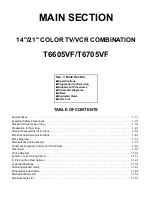
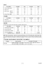
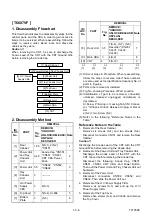
T6605SP
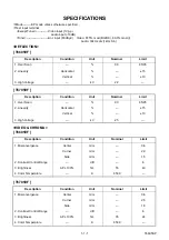
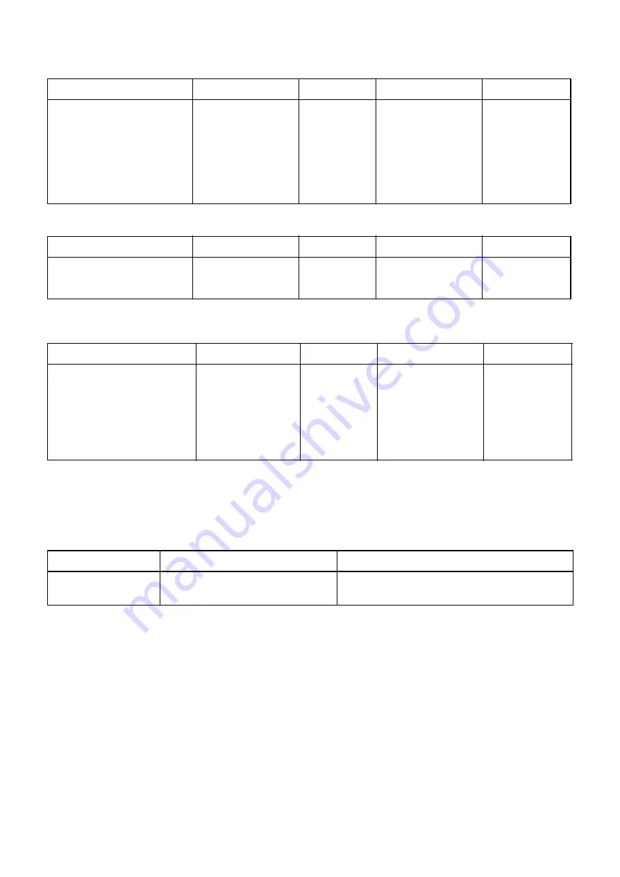
<VCR>
<TUNER>
<AUDIO>
All items are measured across 8
Ω
resistor at speaker output terminal.
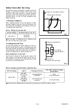
Note: Nominal specifications represent the design specifications. All units should be able to approximate these.
Some will exceed and some may drop slightly below these specifications. Limit specifications represent the abso-
lute worst condition that still might be considered acceptable. In no case should a unit fail to meet limit specifica-
tions.
<TV NORM, TUNER SENSIVITY, RECEPTIVE TV CHANNELS>
Description
Condition
Unit
Nominal
Limit
1. Horizontal Resolution
(R/P)
Line
230
200
2. Jitter (Low)
(R/P)
µ
S
0.05
0.2
3. S/N Chroma AM(SP)
(R/P)
dB
38
33
PM(SP)
(R/P)
dB
36
33
4. Wow & Flutter (RMS)
(R/P)
%
0.25
0.5
Description
Condition
Unit
Nominal
Limit
1. Video S/N
—
dB
45
40
2. Audio S/N (W/LPF)
—
dB
43
40
Description
Condition
Unit
Nominal
Limit
1. Audio Output Power (Max.)
(R/P)
W
1.0
0.8
2. Audio S/N (W/LPF)
(R/P)
dB
40
36
3. Audio Distortion (W/LPF)
(R/P)
%
3.0
5.0
4. Audio Freq. Response
(-20dB Ref. 1kHz)
200Hz (R/P)
6kHz (R/P)
dB
dB
—
—
5.0/-10
5.0/-10
TV Norm
Tuner Sensivity
Receptive TV Channels
PAL-B/G
NOM: VHF 46dB
µ
V / UHF 47dB
µ
V
MAX: VHF 53dB
µ
V / UHF 56dB
µ
V
E2 - E12, IA - IH, E21 - E69, S01 - S03, Z+1,
Z+2, S1 - S41, gap2
Summary of Contents for T6605VF
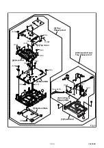
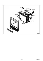
Page 17: ...1 5 4 T6605DC Fig 4 S 10 S 10 S 10 S 10 Anode Cap 10 CRT CRT CBA...
Page 22: ...1 5 9 T6705DC Fig 4 S 10 S 10 S 10 S 10 Anode Cap 10 CRT CRT CBA...
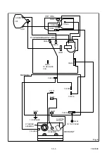
Page 41: ...Main 1 5 Schematic Diagram 1 8 3 1 8 4 T6605SCM1...
Page 42: ...Main 2 5 Schematic Diagram 1 8 5 1 8 6 T6605SCM2...
Page 64: ...1 14 5 T6605PEX Packing T6605VF S3 S6 X3 S2 X4 X1 TAPE S1 FRONT S4 X2 3...
Page 65: ...1 14 6 T6605PEX T6705VF S3 S6 X3 S2 X4 X1 TAPE S1 FRONT S4 X2 3...
Page 99: ...2 4 9 Z13PDA Fig DM16 43 41 42 L 13 Fig DM17 44 45 Slide P 9...