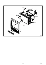


1-5-8
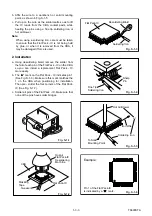
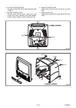
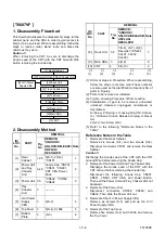
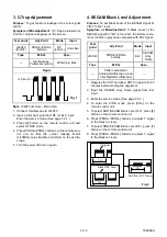
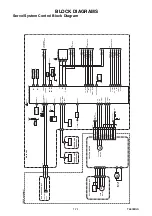
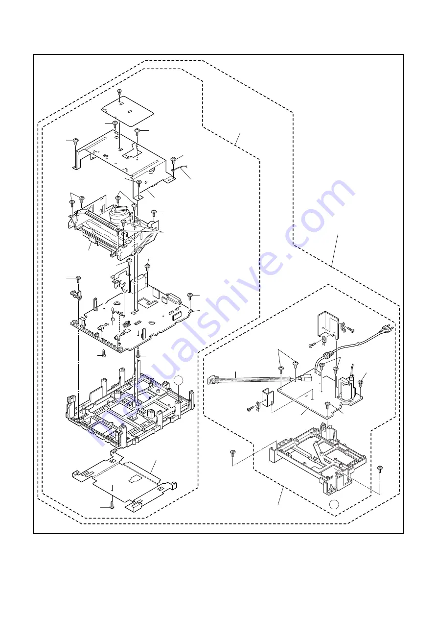
T6705DC
(S-7)
(S-8)
A
A
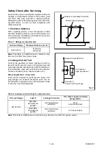
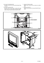
Fig. 3
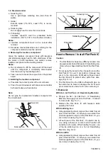
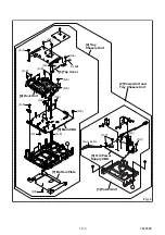
[2] Power Unit and
Tray Chassis Unit
[5] H.V./Power
Supply CBA
(S-3)
(S-3)
(S-3)
[3] Power Unit
Power Button
(S-3)
(S-4)
(S-4)
(S-5)
[7] Bottom Plate
(S-4)
CL604
(S-4)
(S-4)
(S-6)
(S-9)
(S-9)
(S-9)
(S-9)
(S-6)
(S-6)
(S-6)
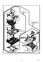
[8] Deck Unit
[6] Top Cover
[9] Main CBA
[4] Tray
Chassis Unit
Summary of Contents for T6605VF
Page 17: ...1 5 4 T6605DC Fig 4 S 10 S 10 S 10 S 10 Anode Cap 10 CRT CRT CBA...
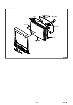
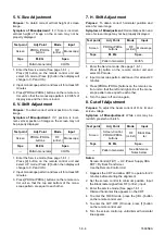
Page 22: ...1 5 9 T6705DC Fig 4 S 10 S 10 S 10 S 10 Anode Cap 10 CRT CRT CBA...
Page 41: ...Main 1 5 Schematic Diagram 1 8 3 1 8 4 T6605SCM1...
Page 42: ...Main 2 5 Schematic Diagram 1 8 5 1 8 6 T6605SCM2...
Page 64: ...1 14 5 T6605PEX Packing T6605VF S3 S6 X3 S2 X4 X1 TAPE S1 FRONT S4 X2 3...
Page 65: ...1 14 6 T6605PEX T6705VF S3 S6 X3 S2 X4 X1 TAPE S1 FRONT S4 X2 3...
Page 99: ...2 4 9 Z13PDA Fig DM16 43 41 42 L 13 Fig DM17 44 45 Slide P 9...


