Duomo gas proving systems
-
Duomo gas detection
-
Duomo carbon dioxide sensors
-
Duomo ventilation interlocks
-
Are available direct or from all major stockists
Configuring The BX116
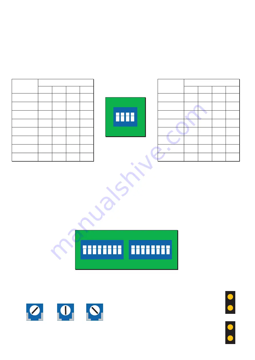
The BX116 has three banks of DIP switches on the PCB. The set of switches on the rear of the front of the unit is used to
control the LED's that represent the number of sensors connected to the system. The remaining switches are used to
activate/deactivate the sensors themselves.
Controlling the LED's that represent connected sensors
The front of the BX116 has two banks of eight LED's that represent each connected sensor. The LED's cycle through each
connected sensor and the associated gas concentration is displayed above. The table below shows what combination the
DIP switches must be in to display and cycle through the correct number of LED's.
Pre alarm threshold
The pre alarm on the BX116 can be altered to one of three
thresholds;
13% LEL
15% LEL
18% LEL
Turn the potentiometer all the way to the right for 18%, to
the middle for 13% and all the way to the left for 8%
Changing display units
The BX116 can display the current gas
concentration detected in either LEL or
ppm.
This is done by closing one of two jumpers
on the PCB on the rear of the door of the
unit. Closing the upper jumper sets the unit
to LEL. Closing the lower jumper sets the
unit to ppm.
Disabling or uninstalling sensors
The BX116 can accept up to 16 sensors, divided into two zones. You should deselect the DIP switch for any sensors that are
not connected. Not doing so could cause the unit to go into fault. If you experience a faulty sensor, disabling it via its
corresponding switch will return the BX116 to normal operation, allowing you to fix the sensor with uninterrupted
coverage. PLEASE NOTE: In order to turn the sensor ON, the switch must be in the DOWN position.
For example if you have 11 sensors connected, the DIP switches would need to be set to the following;
ON - OFF - ON - OFF
Y
4
3
ON
2
1
Y
ON
1 2 3 4 5 6 7 8
Y
ON
1 2 3 4 5 6 7 8
Sensor
Zone 1
Micro Switch
1
1
OFF
OFF
OFF
OFF
OFF
OFF
OFF
OFF
2
3
4
2
3
4
5
6
7
8
OFF
OFF
OFF
OFF
ON
ON
ON
ON
ON
ON
ON
ON
ON
ON
ON
ON
OFF
OFF
OFF
OFF
OFF
OFF
OFF
OFF
Sensor
Zone 2
Micro Switch
9
1
2
3
4
10
11
12
13
14
15
16
OFF
OFF
OFF
OFF
ON
ON
ON
ON
ON
ON
ON
ON
ON
ON
ON
ON
ON
ON
ON
ON
ON
ON
ON
ON
OFF
OFF
OFF
OFF
OFF
OFF
OFF
OFF


