9
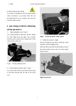
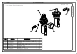
● Pull rightward the switch1
(
Fig25 1c
)
, the tool
head must rotate counterclockwise by 180°
● Pull leftward the switch1
(
Fig25 1d
)
, the tool
head must rotate clockwise by 180°
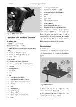
● Pull rightward the switch 2
(
Fig 23
)
the tool
arm must move rightwards.
● Pull leftward the switch 2
(
Fig 23
)
the tool arm
must move leftwards.
2 Check if the movement directions of the carriag
(
5
)
and tool arm
(
7
)
is correct
(
see Fig 23
):
●
Push leftward switch 3, carriage move
leftward.
●
Push rightward switch 3, carriage move
rightward.
●
Push upward the switch 3, the tool arm move
upward
●
Push downward the switch3, the tool arm
move downward
3 Check if the function of the center chuck is
correct
(
see Fig 22
)
:
●
Push the switch4 leftward, the chuck will
open.
●
Push the switch4 rightward, the chuck will
close.
●
Step the pedal switch at the b side
,
the chuck
will rotate clockwise.
●
Step the pedal switch at the c side
,
the chuck
will rotate counterclockwise
4 Check the vertical movement of the tool arm and
the
rotating
function
of
the
tool
hea
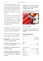
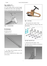
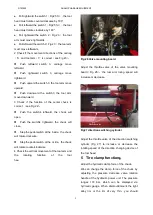
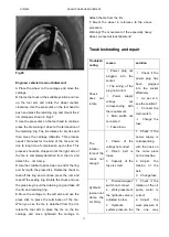
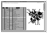
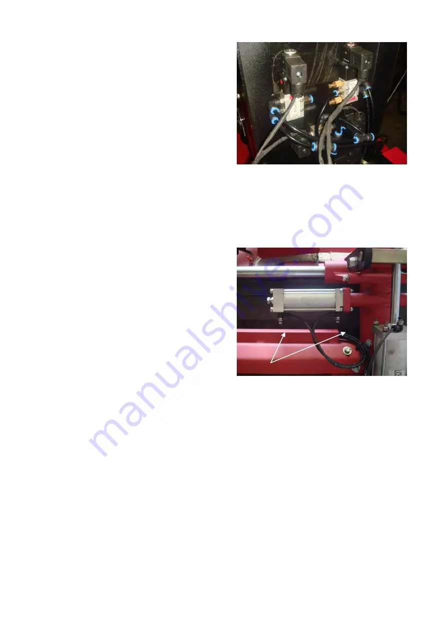
Fig 26 Valve mounting board
Adjust the throttle valve of the valve mounting
board
(
Fig 26
),
the tool arm rising speed will
increase or decrease.
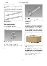
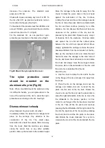
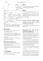
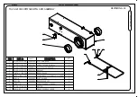
Fig27 direction switching cylinder
Adjust the throttle valve of the direction switching
cylinder (Fig 27) to increase or decrease the
rotating speed of the direction changing device of
the tool head.
5 Tire clamp function
:
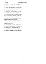
Adjust the hydraulic clamp force of the chuck
:
We can change the clamp force of the chuck by
adjusting the pressure decrease valve rotation
handle of the hydraulic power unit. The pressure
ranges 130 bar, which can be displayed via
hydraulic gauge. When dismount/mount the light
alloy rim or the rim of very thin
,
you should
Throttle valve
Throttle valve
DTM590
DUNLOP GARAGE EQUIPMENT


