background image

13

INDUCED DRAFT HIGH EFFICIENCY BOILERS 

Maximum Horizontal Vent Length For Stainless     

Steel Vent Pipe - 30’ Plus One 90º Elbow Plus 

Vent Terminal

Minimum Horizontal Vent Length - 2’ Plus One 

90º Elbow Vent Termination

Additional  elbows  are  equivalent  to  6  feet  of 
straight pipe for 4” diameter 90° elbow or 3 feet 
of straight pipe for 3” diameter 90° elbow 2, 3, 
4, 5, Section Boilers use 3” vent pipe for 6, 7 
Section Boilers use 4” vent pipe.

CHOICE OF VENT PIPE MATERIAL

a) U.L. Listed Z-Flex Z-Vent Stainless Steel Vent Pipe.
b) U.L. Listed Heat-Fab Saf-T-Vent Stainless SteelVent Pipe.
c) U.L. Listed Flex-L Star-34 Stainless Steel VentPipe.
d) U.L. Listed ProTech Systems FasNSeal Stainless Steel Vent 

Pipe.

hoRIZoNtAl VeNtING ACCeSSoRIeS pARt NumBeRS

Description 

 Part Number

3" side Wall Vent Hood (Tjernlund VH-1-3")

14629010

4" side Wall Vent Hood (Tjernlund VH-1-4")

14629011

3" Thimble (Simpson 905295)

14629013

4" Thimble (Simpson 915295)

14629014

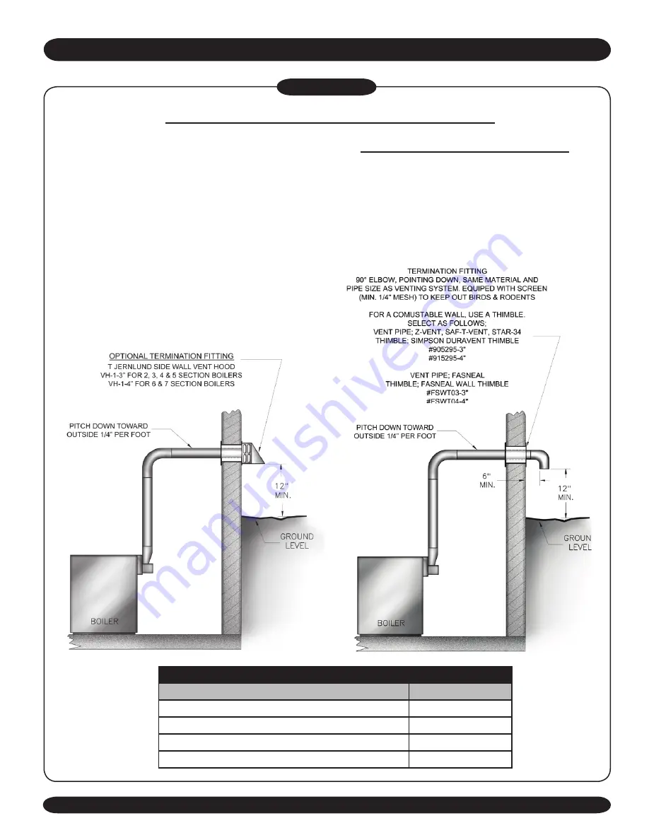
hoRIZoNtAl VeNtING INStRuCtIoNS 


Figure #9

Summary of Contents for XEB-2

Page 1: ...INSTALLATION MANUAL DUNKIRK BOILERS 85 Middle Rd Dunkirk NY 14048 www dunkirk com An ISO 9001 2000 Certified Company P N 14683001 Rev 2 1 02 08 XEB Series Gas Fired Hot Water Induced Draft BOILERS ...

Page 2: ...ed at high altitude by using a certified field conversion kit resulting in a 10 de rate Heating Capacity based on D O E Department of Energy test procedure Figure 1 This boiler cannot be used with all types of chimneys Read these instructions carefully before installing These Gas Fired Hot Water Boilers are low pressure sectional cast iron boilers Design Certified by C S A Canadian Standards Assoc...

Page 3: ...y CSA Canadian Standards Association for use with Natural and Propane Gases They are constructed and hydrostatically tested for a maximum working pressure of 50psi pounds per square inch in accordance with A S M E American Society of Mechanical Engineers Boiler and Pressure Vessel Code Section IV Standards for cast iron heating boilers of 4 for each 1 000 feet above sea level Consult the National ...

Page 4: ...tional Fuel Gas Code for further information including approved methods for reducing clearances in large room 5 Equipment shall be installed in a location in which the facilities for ventilation permit satisfactory combustion of gas proper venting and maintenance of ambient temperature at safe limits under normal conditions of use Equipment shall be located so as not to interfere with proper circu...

Page 5: ...lation air must be in accordance with the National Fuel Gas Code ANSI Z223 1 latest revision or applicable provisions of the local building codes WARNING Be sure to provide enough fresh air for combustion Enough air insures proper combustion and assures that no hazard will develop due to the lack of oxygen EXAMPLE 2 Boiler Located in Confined Space A AllAir from Inside the Building The confined sp...

Page 6: ...ndonecommencing within 12 inches of the bottom of the enclosure shall be provided The openings shall communicate directly or by the ducts with the outdoors or spaces crawl or attic that freely communicate with the outdoors a Wheredirectlycommunicatingwiththeoutdoors or where communicating to the outdoors throughverticalducts eachopeningshallhave a minimum free area of 1 sq in per 4000 Btu per hour...

Page 7: ...r is shipped assembled You need only to install the circulator ball valves the relief valve with a drain line to carry any water to a drain and the drain valve 2 Install Relief Valve on 3 4 pipe nipple in tapped opening in the left end section Connect a drain line of the same pipe size 3 4 to carry any water away to a drain No shutoff of any description shall be placed between the safety relief va...

Page 8: ...type devices per manufacturers specific instructions Figure 6 PIPING ARRANGEMENTS FOR BOILER WHEN USED IN CONNECTION WITH REFRIGERATION SYSTEM When the boiler is used in connection with refrigeration systems it shall be installed so that the chilled medium is piped in parallel with the heating boiler with appropriate valves to prevent the chilled medium from entering the heating boiler Figure 6 If...

Page 9: ...ection to gas vents or chimneys vent installations shall be in accordance with the National Fuel Gas Code ANSI Z223 1 latest revision and applicable provisions of the local building codes CHECK YOUR CHIMNEY This is a very important part of your heating system It must be clean the right size properly constructed and in GOOD CONDITION No boiler can function properly with a bad chimney 1 Use local co...

Page 10: ...ey flue Use a sealed in thimble for the chimney connection 11 The sections of vent pipe should be fastened with sheet metal screws to make the piping rigid Use stovepipe wires to support the pipe from above 12 Do not connect to fireplace flue 13 Do not install a damper on this boiler MINIMUM VENT PIPE CLEARANCE If the vent pipe must go through a crawl space Type B vent pipe should be used Where ve...

Page 11: ...with a bad chimney Use local codes for installation or National Fuel Gas Code Z223 1 latest revision In Canada follow CSAB149 1 or 2 Installation Codes It is very important to properly size the venting system for induced draft appliances Consult the Vent Sizing Tables in the National Fuel Gas Code ANSI Z223 1 latest revision for correct sizing information In Canada consult the Vent Sizing Tables A...

Page 12: ... Codes Chimney and Vent Pipe Connection When an existing boiler is removed from a common venting system the common venting system is likely to be too large for proper venting of the appliances remaining connected to it At the time of removal of an existing boiler the following steps shall be followed with each appliance remaining connected to the common venting system placed in operation while the...

Page 13: ...se 3 vent pipe for 6 7 Section Boilers use 4 vent pipe CHOICE OF VENT PIPE MATERIAL a U L ListedZ FlexZ VentStainlessSteelVentPipe b U L Listed Heat Fab Saf T Vent Stainless SteelVent Pipe c U L ListedFlex LStar 34StainlessSteelVentPipe d U L Listed ProTech Systems FasNSeal Stainless Steel Vent Pipe HORIZONTAL VENTING ACCESSORIES PART NUMBERS Description Part Number 3 side Wall Vent Hood Tjernlund...

Page 14: ...tion Fitting For all vent pipe materials you may use either a a 90 elbow pointing down fitted with a minimum 1 4 mesh screen to keep out rodents and birds The elbow shall be of the same material and size as vent pipe The elbow exit should be at least 6 away from exterior wall as shown in Figure 9 or b Tjernlund VH 1 Series side wall vent hood For 2 3 4 5 section boilers use VH 1 3 For 6 7 section ...

Page 15: ...ate with caulk or silicone and fasten to the wall with screws or nails c For single wall pipe through non combustible walls the hole through the wall need only be large enough to maintain the pitch of the vent pipe and provide proper sealing A thimble is not required for single wall pipe passing through noncombustible walls d The venting system shall terminate at least 3 feet above any forced air ...

Page 16: ...ing silicone bead For 3 vent pipe runs begin with the male end of the vent pipe over the boilers induced draft blower outlet For 4 vent pipe runs begin with a 6 length of 3 Z Vent 02SVEPxx0306 over the boiler s induced draft blower outlet to which an even bead of high temperature silicone sealant should be applied Then connect the 3 Z Vent to a Z Vent 3 to 4 reducer 02SVERxx0403 Then continue the ...

Page 17: ...ery 12 inches 305mm downward away from the boiler to prevent collection of condensate throughout the assembly 6 Allow the sealant to cure for 24 hours before operating the appliance the male end Also run a similar size bead of silicone sealant down the seam weld at the end of each joint 2 Pipes can now be pushed together as far as they will go The seams on the vent pipe should be aligned and orien...

Page 18: ...he vent hood s pipe with a steel gear clamp 1 Apply the high temperature silicone around the male end of the pipe in an even bead Silicone bead should be approximately from the end of the male end Also run a similar size bead of silicone sealant down the seam weld at the end of each joint 2 The seams on the vent pipe should be aligned and oriented upward in all horizontal vent pipe runs 3 Insert t...

Page 19: ...all sheathing using hollow wall anchors Each support will be 1 inch lower than the previous support when spaced 6 feet apart c Flex L stainless steel vent piping requires a loose fitting metal strap or similar support at each joint at a maximum of 4 feet between supports d ProTech stainless steel vent piping requires one loose fitting FasNSeal support strap FSSH for every 6 of horizontal vent 10 I...

Page 20: ...et For 4 vent pipe runs begin with the galvanized 3 to 4 increaser fitting included in the boiler s parts bag over the induced draft blower outlet Then follow by placing the female end of the 4 vent pipe over the increaser fitting When joining pieces of single wall galvanized vent pipe a substantial bead of silicone should be used at the joint to insure a leakproof connection Horizontal venting wi...

Page 21: ...ing rules apply 1 Use only those piping materials and joining methods listed as acceptable by the authority having jurisdiction or in the absence of such requirements by the National Fuel Gas Code ANSI Z223 1 latest revision In Canada follow the CSA B149 1 and 2 Installation Codes for Gas Burning Appliances and Equipment 2 All pipe compound must be resistant to liquefied petroleum gas 3 Install gr...

Page 22: ... terminals B1 and B2 4 When blower gets up to speed and blower suction pressure reaches pressure switch setpoint pressure switch contacts close sending 24 volts to intermittent pilot control from transformer secondary 5 Pilot gas valve opens and spark initiates to light pilot burner 6 When pilot flame is proven spark drops out 7 Main gas valve opens and pilot burner ignites main burners 8 If boile...

Page 23: ...0 60 1 24V LOW VOLTAGE FIELD WIRING BK GND BK PV MV SWITCH PRESSURE ROLLOUT SWITCH W R G PV MV W G R BK TO PILOT VR8204A VR8304M GAS VALVE BT BL AT 140C TRANSFORMER BT B2 MV PV INTERMITTENT PILOT CONTROL MV 24V PV GND L8148A T DRAFT BLUE GND 24V SPARK BL R RED LOW VOLTAGE WIRING LINE VOLTAGE WIRING BLACK WITH TRACER GREEN WHITE BLACK BT W G B G G B W W B INDUCER AQUASTAT THERMOSTAT BURNER 1K 24V 2...

Page 24: ...iler top 2 That the pipe to the tank continuously rises up to the tank so that air can bubble up to it Equipment and Optional Accessories What They Do DIAPHRAGM TYPE EXPANSION TANK The Diaphragm Type Expansion Tank EX TROL takes the place of the conventional expansion tank Carefully read the instructions packed with your EX TROL Tank Assembly The EX TROL Tank comes to you with a 10 12 pounds per s...

Page 25: ...of draining all water from the boiler and system It is often installed in the tapping at the bottom of the left boiler section Or it can be installed in a tee where the return line enters the boiler PRESSURE SWITCH The air pressure switch works on a negative pressure When the blower comes on the air pressure switch operates the intermittent pilot and gas valve The air pressure switch is factory se...

Page 26: ...ressure gauge Note the position of the hand indicating pressure This should be between 10 and 15 lbs Any lowering of this movable hand below 10 lbs will indicate loss of water due to leakage The automatic fill valve should compensate for this Instructions are packaged with the valve WARNING Never run water into a hot empty boiler 1 This appliance is equipped with an ignition device which automatic...

Page 27: ...rate after several tries turn the gas control knob to OFF and call your service technician or gas supplier 1 Set the thermostat to lowest setting 2 Turn off all electric power to the appliance if servicing is to be performed 3 Depress gas control knob slightly and turn clockwise to OFF position Do not force OPERATING INSTRUCTIONS OFF ON INLET GAS CONTROL KNOB SHOWN IN ON POSITION Figure 13 TO TURN...

Page 28: ...n be changed after you have had some idea how the system works Example If your system does not give quite enough heat in very cold weather you can raise the limit setting to 220 F orange momentarily This is not unusual Remain still when observing the main burner flames Refer to Figure 16 If the flame appearance is not correct check main burner orifices and the burner throat and flame ports for dus...

Page 29: ...eive an excess of air Frequent automatic opening of the relief valve indicates water logging A high boiler temperature accompanied by unusually low radiation unit temperature and knocking indicates excess air in tank To correct either condition close the valve between the boiler and the tank Drain the tank until it is empty Check all the tank plugs and fittings Tighten as necessary Open the valve ...

Page 30: ...open and clear Shake out or blow out all loose dirt in burners Reassemble all parts Seal flue collector and clean Maintaining Your Boiler out plates to sections with silicone sealant 400 F RTV silicone sealant or equivalent Reseal seams between adjacent sections where necessary All joints must be airtight Be sure to check tightness of pilot connections and condition of burner flames after reassemb...

Page 31: ...protection Check relay operation Poor electrical contact Check all control terminals and wire joints Chimney flue is blocked Pressure switch will not close and pilot spark will not operate to start pilot Have your service technician check and correct if necessary Rollout switch blown Have your service technician check heat exchanger for block age Replace rollout switch with exact replacement IF BU...

Page 32: ...pair parts list NOT a packing list KEY NO DESCRIPTION PART NUMBERS FOR 2 Section 3 Section 4 Section 5 Section 6 Section 7 Section 1 24 Volt Gas Valve Natural Gas 14662052 14662052 14662052 14662052 14662058 14662058 2 Pilot Tube With Fitting 43300201 43300201 43300201 43300201 43300200 43300200 3 10 32 x 3 16 Slotted Hex Head Screws 14695301 14695301 14695301 14695301 14695301 14695301 4 Gas Mani...

Page 33: ...16 Slotted Hex Head Screws 14695301 14695301 14695301 14695301 14695301 14695301 4 Gas Manifold 14616020 14616021 14616022 14616023 14616024 14616025 5 Orifice Propane Gas 14615044 14615036 14615036 14615036 14615036 14615036 6 Main Burner Less Pilot Bracket 14615532 14615532 14615532 14615532 14615532 6A Main Burner with Pilot Bracket 14615531 14615531 14615531 14615531 14615531 14615531 7 Pilot ...

Page 34: ...001032AC 730001033AC 730001034AC 730001035AC 730001036AC 730001037AC 10 1 4 Tie Rod 2 Required 14605008 14605001 14605002 14605051 14605053 14605005 11 Nut 1330002 1330002 1330002 1330002 1330002 1330002 12 Section Left End 41000019 41000019 41000019 41000019 41000019 41000019 13 Section Intermediate 41000018 41000018 41000018 41000018 41000018 14 Jacket Top Panel 730001012AC 730001013AC 730001014...

Page 35: ...14662070 9 Induced Draft Blower and Gasket 14626054 10 Pressure Switch 2 3 4 5 Section 14655006 Pressure Switch 6 7 Section 14655005 11 Nipple 1 x 2 14607044 12 Tee 1 x 1 x PF05901 13 Bushing x 1060002 Grundfos Pump UP15 42F CI 006 01 Taco Pump 007 CI 001 03 Isolation Ball Valve 14626043 Rubber Tube Blower to Pressure Switch 1552014 Rollout Switch 14629002 1 x Bushing 1060003 24 V Transformer 1466...

Page 36: ...85 Middle Rd Dunkirk NY 14048 ...

Reviews: