background image

ENGLISH

9

OPERATING INSTRUCTIONS

When the indicating lamp blinks in green or the message
“POWER SAVE” or “OUT OF FREQUENCY” appears on
the screen, there is something unusual about the status of
reception. See “Symptoms That Seemingly Appear to be
Failures.”

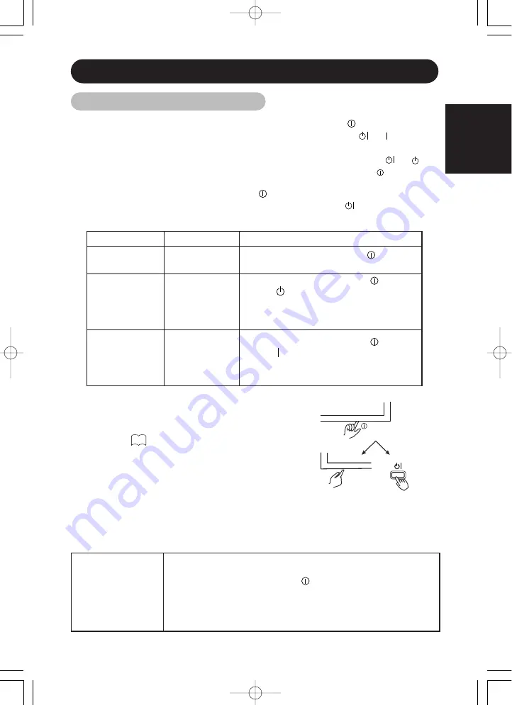
Main power
switch

Main unit

Remote
controller

SUB POWER

Turning Power On and Off

Indicating lamp

Power status

Operating

Off

Off

When the main power switch 

is set to

OFF.

Lights red

Off

(standby)

When the main power switch (

) is ON,

and the 

button on the

remote control or the SUB POWER button
on the underside of the front of the frame
is OFF.

Lights or blinks

green

On

When the main power switch (

) is ON,

and the 

button on the remote control or

the SUB POWER button on the underside
of the front of the frame is ON.

23

TIPS

• Avoid repeatedly turning the monitor on and off at short time

intervals. Failures might result from such operation.

• Turn off the main power switch (

) before leaving the monitor out

of use for an extended period of time.

• If a power failure occurs while the main unit is running, it would be

powered on upon recovery from the failure.  Turn off the unit main
power switch before leaving the main unit.

To turn the monitor power ON, press the main power switch (

) on the monitor

main unit to ON, and then press the SUB POWER button or the 

or  button on

the remote control.

To turn the monitor power OFF, press the SUB POWER button or the 

or 

button on the remote control, and then press the main power switch ( ) on the
monitor main unit to OFF.

During normal use, the main power switch (

) is set in the ON position, and the monitor

can then be turned ON/OFF using the SUB POWER button or the 

button on the

remote control.

00u24121UE  01.9.19 11:50 AM  ページ 9

Summary of Contents for ImagePro P42

Page 1: ...y Model P42 Read the instructions inside carefully Keep this user manual for future reference Serial No ______________________ The serial number is located on the rear of the monitor USER S MANUAL P42 with optional stand ...

Page 2: ......

Page 3: ...f your properties WARNING CAUTION Fire or electric shock may cause death or serious injury unless you follow the instruction below WARNING If something smells strange or smoke comes from the monitor Turn off the monitor and disconnect the power plug from the mains immediately Contact service center after confirming that the smoking has stopped If you continue to operate the monitor with such abnor...

Page 4: ... service center Fire or electric shock may cause death or serious injury unless you follow the instruction WARNING The enclosed power cord must be used Failure to do so may cause electric shock hazard or fire hazard In USA Canada use a UL LISTED CSA LABELLED or CERTIFIED power cord set meeting the following specifications Rating min 125V 10A Length max 3 0m Type SVT or SJT Plug type NEMA 5 15P fig...

Page 5: ...the monitor with two persons Handle with care when you move the monitor particularly take care of glass screen When you disconnect the power plug You have to grasp the power plug itself do not pull the power cord If you pull the power cord you may damage it and it may cause a fire or an electric shock Do not touch the power plug just after disconnecting it from the mains or you may receive electri...

Page 6: ...ation For complete isolation from the mains remove the power cord from the monitor or from the wall socket Protection against Minimum number of fuses or circuit breaker poles Location Case A Equipment to be connected to POWER SYSTEMS with earthed neutral reliably identified except for Case C below Earth faults 1 Phase conductor Overcurrent 1 Either of the two conductors Case B Equipment to be conn...

Page 7: ...Please watch the monitor in downward direction Note on image retention The plasma monitor illuminates phosphor to display images The phosphor has a finite illumination life After extended periods of illumination the brightness of the phosphor would be degraded to such extent that still images would image retention that part of the screen as grayed out images Tips to prevent such image retention ar...

Page 8: ...s for the monitor Use the attached signal cable when you connect the monitor with PC equipment Do not use other signal cables Confirm the connector is fixed tightly when the signal cable is connected Also confirm the screws on the connector are tightened Plug the power cord of the monitor into a different socket from that for other equipment such as Radio etc Use a plug with ground terminal and ma...

Page 9: ...g conditions are met Video inputs The input signal amplitude must not exceed the specified level CAUTION Changes or modifications not expressly approved by the party responsible for compliance could void the user s authority to operate the equipment Declaration of Conformity According to 47CFR Part 2 and 15 for Class B Personal Computers and Peripherals and or CPU Boards and Power Supplies used wi...

Page 10: ...00u14121U 01 9 19 11 58 AM ページXXXVI ...

Page 11: ...ned in this manual may be trademarks or registered trademarks of their respective owners SAFETY GUIDELINES I CONTENTS 1 FEATURES 2 STANDARD ACCESSORIES 2 INSTALLATION INSTRUCTIONS 3 Installation 3 Anti tumble measures 3 Component Names 4 Installation and Cabling 6 Handling the Remote Controller 8 OPERATING INSTRUCTIONS 9 Turning Power On and Off 9 Input Selection 10 Volume Adjustment 10 Sound Mute...

Page 12: ...olution of 1024 H x 1024 V pixels creates a high definition large screen aspect ratio 16 9 and low profile flat display Free from electromagnetic interferences from geomagnetic sources and ambient power lines the panel produces high quality display images free from color misconvergence and display distortion Multimedia input support The monitor is provided with a mini D Sub connector and a BNC con...

Page 13: ...empt this work yourself Ask your dealer to provide the name of a qualified installer In order to prevent an internal temperature increase maintain a space of 10cm 4 inches For a desktop set up or more between the sides and other objects such as walls etc so that the ventilation holes are not blocked WARNING CAUTIONS Cord or chain Clamp 10cm 4 inches or more Two places Wood screw Securing to a wall...

Page 14: ...on MENU button INPUT SELECT button SELECT button Adjustment buttons are located on the bottom The inner side of the cover is provided with indications to distinguish the adjustment buttons SUB POWER button Component Names 9 10 12 12 10 9 9 The main power switch is located at the back on the lower surface The stand is an Optional 00u24121UE 01 9 19 11 50 AM ページ 4 ...

Page 15: ...ZE button POWER ON OFF button MUTE button MENU button VOLUME button SELECT button 9 10 12 10 12 11 External speaker terminals 7 RECALL button 11 RGB VIDEO button 10 POWER OFF button 9 POWER ON button 9 Handgrips Caution when moving the main unit As this product is heavy whenever it is moved two people are required to transport it safely Whenever the unit is moved it should be lifted forwards using...

Page 16: ... consult your dealer after reading the section Signal Input 5 Insert one end of the power cable included into the rear panel power cable connector and the other end into a power socket 6 Turn on the monitor then the PC to make sure that a display image appears on the monitor screen For instructions on turning on the monitor and adjusting its display images see Operating Instructions to Installatio...

Page 17: ...ent output terminals To component input terminals To audio video input terminals To audio input terminals Video equipment such as a video disc player a DVD player and a video camera Monitor rear panel External Monitor Power cable Power cable connector Red R AUDIO IN R L MONO AUDIO IN COMPONENT COMPOSITE S VIDEO 2 VIDEO 1 R PR CR PB CB Y IN IN OUT L MONO Speaker R Speaker L White L Red R White L Re...

Page 18: ... old batteries together The batteries could explode or leak resulting in fires physical injury or stains When loading batteries observe their correct polarities as marked on the product If loaded in the wrong direction the batteries could explode or leak resulting in fires physical injury or stains TIPS Do not drop or impact the remote controller Do not splash the remote controller with water or p...

Page 19: ... frame is ON 23 TIPS Avoid repeatedly turning the monitor on and off at short time intervals Failures might result from such operation Turn off the main power switch before leaving the monitor out of use for an extended period of time If a power failure occurs while the main unit is running it would be powered on upon recovery from the failure Turn off the unit main power switch before leaving the...

Page 20: ...tically VOLUME VOLUME VOLUME VOLUME ENGLISH 10 OPERATING INSTRUCTIONS continued Main unit Remote controller VOLUME VOLUME VOLUME RGB1 D sub input When using INPUT SELECT RGB2 BNC input VIDEO1 composite or S input VIDEO2 COMPONENT input Input Selection Remote controller Main unit RGB 2 RGB 1 VIDEO 2 VIDEO 1 INPUT SELECT Volume Adjustment 12 14 VOLUME 30 Sound volume setting Adjustment status guidan...

Page 21: ...es of the input signal will be displayed in a guidance image For RGB input only While the guidance is on display press the key to narrow the difference between darkness and brightness While the guidance is on display press the key to widen the difference between darkness and brightness You can also adjust the contrast setting via the on screen display system The contrast adjustment mode will exit ...

Page 22: ... to exit to the original menu For information on adjusting and setting choices see to Press the MENU button once again to exit the MAIN MENU The MAIN MENU will close automatically when no keys are entered for 10 seconds ENGLISH 12 OPERATING INSTRUCTIONS continued MAIN MENU PICTURE SOUND DISPLAY FUNCTION Remote controller MENU PICTURE MENU CONTRAST 127 BRIGHTNESS 0 COLOR 0 TINT 0 SHARPNESS 0 PICTUR...

Page 23: ...suit the ambient brightness BRIGHTNESS Black is subdued for increasedoverall darkness Black is set off for increased overall brightness Adjust to prevent black from spreading across the screen COLOR Lightens colors Darkens colors Adjust for desired density somewhat for lighter colors for a natural look TINT Enhances red and weakens green Enhances green and weakens red Adjust for a nice looking ski...

Page 24: ...RMAL 20 10 RGB Normally set to 0 7 V If white is found to spread across the screen set to 1 0 V Set to 0 7 V Set to 1 0 V VIDEO ENHANCE Set to OFF Set to ON ON enhances vertical lines Normally set to ON R GAIN Red is weakened Red is strengthened Sets the color adjustment selected by the user with COLOR SELECT USER mode takes effect automatically when an attempt is made to set a gain G GAIN Green i...

Page 25: ... INITIALIZE Clear the user signal preset data Set to YES Clears all DISPLAY MENU adjustment values exept DISPLAY AREAand exits to the DISPLAY MENU Set to NO Exits to the DISPLAY MENU without clearing the menu adjustment values RGB DISPLAY MENU DISPLAY AREA NORMAL AUTO ADJUST MANUAL ADJUST INTERPOLATION LINEAR WIDE MODE OFF DISPLAY INIT RETURN NORMAL MAIN MENU PICTURE SOUND DISPLAY FUNCTION Display...

Page 26: ...ghtly to right Adjust for clear character visibility MAIN MENU PICTURE SOUND DISPLAY FUNCTION DISPLAY MENU DISPLAY AREA NORMAL AUTO ADJUST MANUAL ADJUST INTERPOLATION LINEAR DISPLAY INIT RETURN RGB MANUAL ADJUST MENU H POSITION 0 V POSITION 0 CLOCK 0 PHASE 0 RETURN RGB DISPLAY MENU VIDEO MAIN MENU PICTURE SOUND DISPLAY FUNCTION DISPLAY MENU DISPLAY SIZE PANOR V POSITION 0 V SIZE 0 DISPLAY INIT RET...

Page 27: ... FULL For component HD3 1035i 1080i 720p signals the display mode is not selectable If an S1 or S2 image is input from the S image of video1 the S1 image would be set to FULL and the S2 image would be set to MOVIE1 Displays by Selecting the DISPLAY SIZE VIDEO input When you want to Set the display size to Input signal Display screen Remarks Play a 4 3 image in a 16 9 screen faithfully 4 3 Blanking...

Page 28: ...only PC MOVIE The mode function added to the Function Menu allows for a smooth playback of movies from 60 Hz XGA input when it is set to MOVIE Normally keep the function menu set to PC OFF mode Set it to MOVIE ON when playing movies LINE INTP Set to OFF Set to ON Set to ON when playing a 3D video disc Set to OFF in most cases 3D COMB Set to OFF Set to ON Set to OFF if video images appear unnatural...

Page 29: ...N Cb Cr Pb Pr VIDEO FUNCTION MENU LANGUAGE ENG AUTO FREQ ON LINE INTP OFF 3D COMB ON COMPONENT VIDEO SYSTEM AREA1 SCREEN SAVER RETURN VIDEO Selected characters Setup hint ORBITER Set to OFF Set to ON Set to ON when high image retention potential exists such as static or still image displayed long period of time MOVING DOTS 1 3 2 Adjust as desired Reduces the amount of movement Increases the amount...

Page 30: ...ction Three dimensional Y C separation HD signal Language selection VOLUME BALANCE TREBLE BASS MUTE LEVEL AUTO FREQ LINE INTP 3D COMB COMPONENT LANGUAGE One set can be recorded During normal signal reception Contrast Brightness Color temperature Gamma correction Input signal level CONTRAST BRIGHTNESS COLOR SELECT GAMMA VIDEO LEVEL One set can be recorded during common RGB1 RGB2 input one set of tw...

Page 31: ...IZE VIDEO1 VIDEO2 Changes in the signal status are displayed on the screen as they arise RGB1 D SUB H 46 5kHz V 60 0Hz POWER SAVE OUT OF FREQUENCY Either VIDEO or S VIDEO is displayed on VIDEO input Signal Check Status Display Action The input signal was switched or the RECALL button was pressed after AUTO FREQ was turned on The input terminal and the horizontal and vertical frequencies are displa...

Page 32: ...uce the power consumed by the sunit Video signal Yes No Screen display Active normal display Blank no video Operation mode On Off Indicating lamp Lights green Blinks green Power consumption 360W Sound off 5W or less Sound Mode If you press the MENU button while the monitor has power save mode turned off sound output is enabled by cancelling the off setting of power save mode When the monitor enter...

Page 33: ...is not received normally Check to see if the input signal matches the monitor specifications Check the way the signal cable is connected The power indicating lamp is normally lit but no picture Check the contrast and brightness settings adjust them for higher contrast and brightness Check the way the signal cable is connected The display image appears flowing slantwise Text displayed across the sc...

Page 34: ...ses this may cause vertical stripes to appear because of failure to light Please note that this is not a malfunction Coarse horizontal stripes appear in FULL display Adjusting the phase will reduce the horizontal stripes RGB input The display dims to make the picture invisible during special playback of a VCR FF REW This condition may occur when the unit is connected to a VCR with component output...

Page 35: ...nt procedure 1 Press MENU button to open the MAIN MENU 2 Press SELECT button several times to choose DISPLAY 3 Press to open the DISPLAY MENU 4 Press to choose AUTO ADJUST 5 Press ADJUST OK Adjust the by displaying a fine pattern such as a character string or vertical streak pattern across the screen If AUTO ADJUST does not work well 6 Press MENU button to open the MAIN MENU 7 Press SELECT button ...

Page 36: ... the by displaying a fine pattern such as a character string or vertical streak pattern across the screen If AUTO ADJUST does not work well 6 Press MENU button to open the MAIN MENU 7 Press SELECT button several times to choose DISPLAY 8 Press to open the DISPLAY MENU 9 Press to choose MANUAL ADJUST 10 Press to open the MANUAL ADJUST MENU 11 Press several times to choose PHASE Adjust the phase by ...

Page 37: ...24kHz to 107kHz vertical 50Hz to 85Hz 1080 50i 1080 60i NTSC NTSC 4 43 M PAL PAL N PAL SECAM 480 60i 480 60p 720 60p 1080 60i 1035 60i 575 50i Sync signals H V separate TTL level 2KΩ H V composite TTL level 2KΩ Sync on green 0 3 Vp p 75Ω Video output Signal Through output BNC for VIDEO1 input signals Recommended Signal 27 modes 10 modes Audio output terminal 8W 8W 8Ω Input power AC100 120 200 240V...

Page 38: ...lowing priority order Sync signal type Priority H V separate sync 1 H V composite sync 2 sync on Green 3 RGB terminal BNC connector V sync H sync or H V composite sync G video or sync on green R video B video S input connector pin specifications Serial connector pin specifications Pin Input signal Remarks 1 No connection 2 RXD Unit PC 3 TXD Unit PC 4 No connection 5 GND Unit GND PC GND 6 No connec...

Page 39: ...9 800 X 600 75 00 46 88 49 50 10 800 X 600 85 06 53 67 56 25 11 1024 X 768 60 00 48 36 65 00 12 1024 X 768 70 07 56 48 75 00 13 1024 X 768 75 03 60 02 78 75 14 1024 X 768 85 00 68 68 94 50 15 1152 X 864 75 00 67 50 108 00 16 1280 X 1024 60 02 63 98 108 00 17 1280 X 1024 75 03 79 98 135 00 18 1280 X 1024 85 02 91 15 157 50 19 1600 X 1200 60 00 75 00 162 00 20 1600 X 1200 75 00 93 75 202 50 21 1600 ...

Page 40: ...correctly with an extremely long front porch or back porch or with an extremely short data display time Front porch Sync width Back porch Blanking width Horizontal timing Horizontal frequency 24 kHz to 52 kHz 0 2 µs or more 1 0 4 0 µs 1 2 µs or more 3 5 µs or more Horizontal frequency 52 kHz to 106 kHz 0 2 µs or more 0 8 3 0 µs 1 1 µs or more 2 3 µs or more Vertical timing 9 µs or more 25 µs or mo...

Page 41: ...oration disclaims all liability for incidental or consequential damage of any kind including all damages arising out of any interruptions in operation of the product and all damages to software No person firm or representative is authorized to assume any obligation or to make any warranty on behalf of the Dukane Corporation other than as stated above THIS LIMITED WARRANTY IS VALID FOR U S A AND CA...

Page 42: ... Division 2900 Dukane Drive St Charles IL 60174 3395 E mail avsales dukane com Phone 630 584 2300 Orders 800 676 2485 Information 800 676 2486 Fax 630 584 5156 Parts Service 800 676 2487 Fax 630 584 0984 Audio Visual Products Part 401 592 00 ...

Reviews: