Duerkopp Adler 4181-1 Instructions For Service Manual Download Page 16

13

1

2

90

o

6

7

9

3

3

6

4

5

A

244

o

2

1

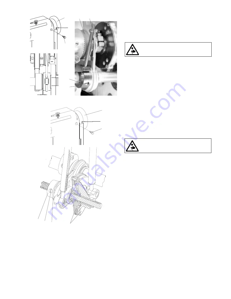
3.5.4.1.3 Setting of the lower eccentric

The rotation of the eccentric (3) must be delayed in phase by

1/4 revolution against the rotation of the eccentric of the stitch

length. This corresponds to the angle of 244

°

 on the handwheel

(1), when the setting pin (4) is put into the eccentric (3) which

is in contact with the indented belt (5).

Caution! Danger of injury!

Switch off the main switch! Before starting the

setting operation, wait until the motor stops!

- Set 244

°

 on the handwheel (1) and lock it with the screw

(2), which is included in the accessory of the machine

(tighten it carefully).

- Put the setting stick (4) into the hole in the eccentric (3) and

prop it from below against the indented belt (5).

- Set eccentric (3) axially.

- Tighten it the utmost the screws of the eccentric (6).

- By means of the handwheel, turn the eccentric (3) into the

marked position and check in this position the clearance

„A“ = 0.05, proceed eventually to its correction by a new

side setting of the eccentric.

3.5.4.1.4 Setting the engagement  and

disengagement of the clutches

The nut (7) is to be side set in such a way that the shifting of

the clutches is done at the moment when the clutch disks (3)

do not move, which means, when they are at the dead center

of their oscillating movement. This corresponds to the angle

90

°

 on the handwheel.

Caution! Danger of injury!

Switch off the main switch! Before starting the

setting operation, wait until the motor stops!

- Loosen the screws of the indented pulley of feeding and

shift it to the left.

- Set the maximum stitch length.

- Set the angle 90

°

 on the handwheel and lock it with the

screw (2). which is included in the accessory of the machine

(tighten it carefully).

- Loosen three screws (6) in the nut (7) and unscrew it by

2 mm to the left.

- Tighten slowly the nut (7), until it strikes against the axial

bearing (9). (At this moment, the tightening moment

increases in jumps) and tighten the screws (6).

- Set the the handwheel on 85

°

 and push the backtacking

lever, the feeder is to turn against the movement of the

needle. Set then the handwheel on 95

°

, the feeder is to be

turned in the sense of the needle movement. If not being

so, correct the side setting of the nut (7). When the clutches

shift too soon, turn a bit the nut (7) to the right and inversely.

- Tighten the screws (6).

- Return the indented pulley in its original place according to

the paragraph 3.6.2.

Summary of Contents for 4181-1

Page 1: ...for service 4181 1 Minerva Boskovice a s Sokolsk 60 CZ 680 17 Boskovice Tel 420 501 453434 453433 494111 Fax 420 501 452165 http www minerva boskovice com Edition 04 2002 Printed in Czech Republic 735...

Page 2: ...of the needle feed and of the lower feed wheel 10 3 5 1 Description 3 5 2 Stitch length mechanism 3 5 2 1 Setting the upper eccentric 3 5 2 2 Setting the prop 3 5 2 3 a Forward and rearward stitch len...

Page 3: ...5 4 1 Replacement of the knife and setting of the distance between the knife and the throat plate insert 5 4 2 Setting of the knife position turning in the sewing direction 5 4 3 Height setting of the...

Page 4: ...wing still remaining possible sources of injury 1 Moving sewing needle risk of injury when sewing with raised pressure foot or top roller because the finger guard is then positioned too high 2 Moving...

Page 5: ...both screws 2 By turning the screws 3 and 4 set the required distance A After having set it tighten carefully the screws By axial shifting of the gear wheel 5 set the axial clearance in such a way th...

Page 6: ...needle 2 After having introduced a suitable screwdriver between the protective sheet and the hook body 3 we shall reduce the play by levering in applying the pressure on the protective sheet in the se...

Page 7: ...1 relative to the gear wheel 2 should ensure the accessibility of the screw 5 at the moment when the hook point 3 comes to lie opposite the needle 4 The wheel 2 is to be set with its gear rim symmetr...

Page 8: ...he take up lever is of aluminum and is provided with a stuck in eye for two threads The connecting rod 2 is mounted on the eccentric pin 3 by means of which the thread mechanism is adjusted for a big...

Page 9: ...of the needle bar height may cause the striking of the hook point against the needle 3 2 4 Side setting of the needle bar holder The correct position of this holder is in such case when the needle bar...

Page 10: ...g The directions E between the needle and the edge of the piercing hole must be the same both at the beginning and at the end of the needle feeding Caution Danger of injury Switch off the main switch...

Page 11: ...ated by means of the nut 1 The force of tensioning the thread is measured by the dynamometer 2 as it is shown on the illustration The size of this force differs according to the category of sewing and...

Page 12: ...1 In this way the whole mechanism im mobilizes 3 4 5 Setting the thread limiter The thread limiter is to be set in such a way that when sewing and passing the thread through the most distant point of...

Page 13: ...ng the setting operation wait until the motor stops Set the angle 90 on the handwheel 2 and lock it with the screw 5 which is included in the accessory of the machine tighten it carefully Insert the s...

Page 14: ...h length excepting the first sewing category where the stitch length of the indicator is 3 mm Caution Danger of injury Switch off the main switch Before starting the setting operation wait until the m...

Page 15: ...y means of the spring washer 11 The plate 5 lining is then pushed by means of a flat profiled spring 2 against the cover of the clutch 1 In the position when the wedge is disengaged the star 4 is push...

Page 16: ...o be side set in such a way that the shifting of the clutches is done at the moment when the clutch disks 3 do not move which means when they are at the dead center of their oscillating movement This...

Page 17: ...2 is to be corrected Caution Dangere of injury Switch off the main switch Before starting the setting operation wait until the motor stops Loosen the screw 3 Loosen the screw 4 Loosen or tighten the s...

Page 18: ...er 5 Loosen the screw 4 and set the required value A 0 2 mm Tighten the screw 4 Setting the force of the top roller 1 In screwing in the screw 2 the force of the top roller is increased and inversely...

Page 19: ...leys are in line The setting thereof is to be done as follows Caution Danger of injury Switch off the main switch Before starting the setting operation wait until the motor stops Loosen the screws 1 o...

Page 20: ...pulley 20 and pull out the feeding shaft 22 from the arm in such a way that it is possible to remove the indented belt 23 from the arm of the machine Replace the belt with a new one and proceed to the...

Page 21: ...chine can be supplied with two types of top roller namely with the diameter of 25 mm and with the diameter of 35 mm The suitability of the diameter used depends on the type of sewing and on the concre...

Page 22: ...m 6 Tighten the screw 1 check the set up clearance 3 6 8 4 Replacement of the top roller When replacing the top roller proceed as follows Caution Danger of injury Switch off the main switch Before sta...

Page 23: ...leaves the space of the bobbin the pressing function of the cam on the winders shaft is interrupted and it moves in the sense of the arrow A fine setting is to be done on an incorporated condition in...

Page 24: ...pposite case when the hook is blocked but the clutch does not disengage the disengaging moment of the clutch is to be reduced in turning the screws to the left Caution The clutch guarantees only one m...

Page 25: ...3 11 1 Tensioning Caution Danger of injury Switch off the main switch Before starting the setting operation wait until the motor stops The belt is correctly tensioned when the opposite sides of the b...

Page 26: ...ubricates the gear of the hook drive 3 13 2 Refilling oil For lubricating the machine oil Esso SP NK 10 is used or other oil with the same quality When putting the machine into operation each mechanis...

Page 27: ...e loosened screw 4 put the holder of the pickup roller 1 up to the stop against the bracket 5 and at the same time the shaft 2 up to the stop against the shaft 3 With the holder 1 held on the stop shi...

Page 28: ...h a way that the measure A 0 1 to 0 5 mm is attained Tighten the screw 4 4 6 Setting the height of the fixed knife and of the retaining spring of the lower thread The fixed knife 1 and the retaining s...

Page 29: ...orce for pulling the thread from the retaining spring is attained The pulling force is tested using a screwdriver 4 according to the illustration Caution The setting of the retaining spring 1 depends...

Page 30: ...he trimming knife lifting The standard size of the trimming knife lift is set up to about 2 5 mm which suits the majority of the sewing operations For trimming difficult materials this lift is to be i...

Page 31: ...hand wheel until the needle enters the throat plate Loosen the screws 2 and 3 and adjust the knife with the holder 4 and the sleeve 5 as required Tighten the screws 2 and 3 Setting for models with inn...

Page 32: ...nd lever 9 in turning it to the right After having engaged the trimming mechanism the hand lever returns into its starting position up to the stop 10 by means of the torsion spring 11 The trimming mec...

Page 33: ...aving switched off the trimming This means the spring should individually be set up in accordance with the thickness and the stiffness of the trimmed material Caution Danger of injury Switch off the m...

Page 34: ...with regard to the protection of the trimming knife cutting edge and to the possibility of injury 6 Lifting the top roller by electromagnet 6 1 Description The core of the electromagnet respectively i...

Page 35: ...r feed direction 7 2 Electromagnet height setting Caution Danger of injury Switch off the main switch Before starting the setting operation wait until the motor stops Set the maximum stitch length Set...

Page 36: ...machine head 9 Drive control panel position sensor The detailed information concerning the drive the control panel and the setting of the position sensor is given in the manual of the drive and of the...

Page 37: ...ewing 3 medium heavy duty sewing In the factory where this machine has been manufactured the machine has been set with respect to the standard parameters of the required sewing category which is desig...

Page 38: ...hread it is necessary to modify the tension of the retaining spring of the trimming device according to the paragraph 4 7 6 When changing markedly the sewing category together with a marked change of...

Reviews: