DSE SD-A27IR User Manual Download Page 6

USER MANUAL

SPEED DOME CAMERA SD-A27IR

Page:

 6     

Page:

 6     

DSE srl - Italy - WWW.DSE.EU  

INSTALLATION OF CAMERA

The 

SD-A series cameras are 

packed 

carefully to prevent damage during transport. First, you must check the received material.

Material check 

The speed dome camera that you have purchased is protected by elements 

Packaging ranging 

carefully removed before using it.
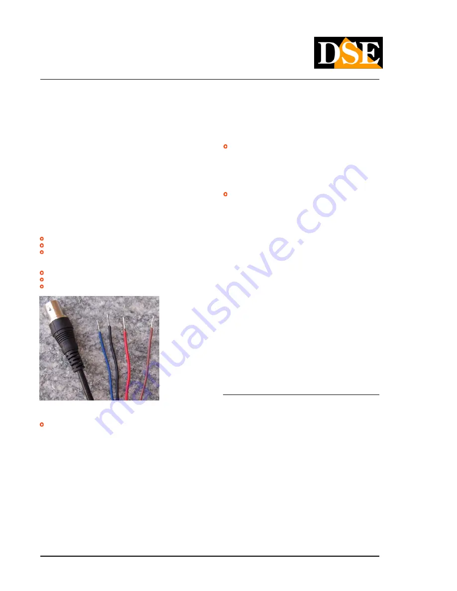
Cable connections  

Each camera Speed ​​Dome SD-A series has a cable fitted with the following connections: 

VERSION 24V AC 

2 cables

 Power RED BLACK 

2 cables

 Power RED BLACK 

video Output

 BNC female 

video Output

 BNC female 

2 Cables

 BUS  

RS485

 BLUE BROWN 

2 Cables

 BUS  

RS485

 BLUE BROWN 

2 Cables

 BUS  

RS485

 BLUE BROWN 

2 Cables

 BUS  

RS485

 BLUE BROWN 

VERSION 12V DC 

1 cable

 feeding with 5.5 mm plug. 

1 cable

 feeding with 5.5 mm plug. 

video Output

 BNC female 

video Output

 BNC female 

2 Cables

 BUS  

RS485

 BLUE BROWN 

2 Cables

 BUS  

RS485

 BLUE BROWN 

2 Cables

 BUS  

RS485

 BLUE BROWN 

2 Cables

 BUS  

RS485

 BLUE BROWN 

To structure a system of Speed ​​Dome cameras must prepare three types of wiring: 

Supply.

 The SD-A27IR cameras come in two versions: with 12VDC power supply with 

Supply.

 The SD-A27IR cameras come in two versions: with 12VDC power supply with 

supply 

24VAC 

(the latter 

with 

power supply included). 

The power supply is 24VAC 

advisable if the wiring is long in order to avoid voltage drops in view of the absorption of the 
camera. 

The 24VAC version is supplied complete with 220VAC / 24VAC. 

In the case of 12VDC power supply is possible to feed the 

camera 

locally with an adapter 

220VAC / 12VDC by at least 3A (not supplied) or 

prepare a 12VDC network with cables with a suitable section so as to avoid excessive 
voltage drop. 

Video connection. 

It is carried out as for any traditional CCTV camera, being the 

Video connection. 

It is carried out as for any traditional CCTV camera, being the 

video signal produced by a composite video camera. You typically use RG59 coaxial cable 
for distances up to 2-300 meters. For longer distances it can carry the video signal on twisted 
pairs using special converters (RE-BNCRJ1 / 2).

Telemetry.

 It is of the serial connection that leads the movement commands to the 

Telemetry.

 It is of the serial connection that leads the movement commands to the 

camera. The SD series cameras use an RS485 serial line (RS485 BUS) which is formed with 
a pair of twisted wires. E 'essential that the two cables are wound between them and 
non-parallel. In principle the RS485 serial line can extend up to 1200 meters in length and 
along it are connected in cascade devices. The section of the cables closely depends on the 
length of the connection: for medium distances is sufficient a section of 0.5 mm, while if it is 
necessary to reach considerable distances (max. 1200 m.) Should be used upper sections of 
1 mm or even 2.5 mm. In carrying out the wiring is recommended to use shielded cable. The 
cameras and the console must be connected in cascade ie entering and exiting from the 
clamps 2 and RS485A RS485B. IS'

important not 

invert the two cables (AB) during the connection of the equipment.    

The order in which the devices are connected to 

BUS has not 

relevance. 

Every 

equipment will be identified by its own unique address, 

adjustable via DIP switches, which 

will properly address the instructions. E 'can be connected to the same BUS up to 256 
cameras.

The console does not require any 

addressing, while for the cameras is necessary to set a different address for each camera, 
as described below. 

The cables to be used for the RS485 line are the BROWN (RS485A) and BLUE (RS485B)

Setting address and baud rate of the cameras  

Each camera must have an address different from the other in order to be identified along 
the BUS. It must also be able to communicate with other devices using the same protocol 
and the same transmission rate (or baud rate). These three parameters: Address, Protocol 
and Baud rate is set via DIP switches on board room and critical to the operation.

Summary of Contents for SD-A27IR

Page 1: ...e horizontal and vertical rotation The control of these engines in one sense or another it is via direct sending of the control voltage via a console connected with a multipole cable typically contain...

Page 2: ...bars SD AST2 Wall Bracket SD AST3 Ceiling Bracket SD AST4 Collar for mounting on a pole for SD brackets AST2 SD AST5 Accessory for mounting at an angle to SD AST2 brackets Console and accessories SD...

Page 3: ...Page 3 Page 3 DSE srl Italy WWW DSE EU DIMENSIONS The camera is provided without the support bracket E must be ordered separately bracket depending on the type of installation planned WITH WALL BRACKE...

Page 4: ...UR function autoflip function to follow the target beyond the vertical It is 180 Registering custom motion sequences It 4 sequences PATTERN Function PRINCIPAL ELECTRICAL FEATURE SD A27IR Supply voltag...

Page 5: ...cess Digital DSP Resolution 540 TV Lines Synchronization internal Signal noise ratio S N ratio Greater than 60 dB Electronic Shutter Speed Shutter 1 50 1 10 000 sec integrated IR illuminator It reache...

Page 6: ...composite video camera You typically use RG59 coaxial cable for distances up to 2 300 meters For longer distances it can carry the video signal on twisted pairs using special converters RE BNCRJ1 2 T...

Page 7: ...the microswitches is the first operation to be performed even before proceed to assembly The camera housing 2 is provided with windows through which You are accessed in blocks of 2 microswitches The w...

Page 8: ...sition ADDRESS SW 1 sw 2 sw 3 sw 4 sw 5 sw 6 sw 7 Sw 8 0 OFF OFF OFF OFF OFF OFF OFF OFF 1 ON OFF OFF OFF OFF OFF OFF OFF 2 OFF ON OFF OFF OFF OFF OFF OFF 3 ON ON OFF OFF OFF OFF OFF OFF 4 OFF OFF ON...

Page 9: ...3 ON ON OFF ON OFF ON OFF OFF 44 OFF OFF ON ON OFF ON OFF OFF 45 ON OFF ON ON OFF ON OFF OFF 46 OFF ON ON ON OFF ON OFF OFF 47 ON ON ON ON OFF ON OFF OFF 48 OFF OFF OFF OFF ON ON OFF OFF 49 ON OFF OFF...

Page 10: ...outlet at the center between the fixing holes The connecting cables pass through the bracket Connect the camera and fasten it to the bracket with the supplied screws Mounting console The movement cont...

Page 11: ...door installations necessary to pay attention to the following general rules Keep wiring at least 50 m away from high medium voltage If you can make runs and cables under the protection of a cornice I...

Page 12: ...h a 27x optical zoom To control the zoom is possible to act on the keyboard ZOOM buttons or TELE WIDE depending on the console If you re using a so called 3D console you can also control the zoom by r...

Page 13: ...the preset 72 This in order to prevent accidental activations of inexperienced personnel These presets are indicated in the table with an asterisk USERS with the preset 72 This in order to prevent ac...

Page 14: ...near scan set to recall the preset 66 71 71 Clear all presets Delete all stored presets 72 Closes EXPERT mode Opens EXPERT mode The perst marked with the symbol require EXPERTS activate this mode in o...

Page 15: ...hours 4 15 sec 8 15 min 12 12 hours TABLE FOR LINEAR SCAN LIMIT see system presets 66 TABLE FOR LINEAR SCAN LIMIT see system presets 66 Set Preset PRESET LIMIT Set Preset PRESET LIMIT Set Preset PRESE...

Page 16: ...o illuminate the darkness falls passing the White black display Default Media 2 Threshold Day Night medium 3 Threshold Day Night low 7 always on Illuminator It defines how they should turn on the LED...

Page 17: ...ess of camera that Yes want program then type 95 and then press CALL or PREVIEW see manual of the console on how to recall a preset In the menu it is carried out by acting on the joystick and the IRIS...

Page 18: ...USER MANUAL SPEED DOME CAMERA SD A27IR Page 18 Page 18 DSE srl Italy WWW DSE EU Map of the configuration menu...

Page 19: ...o the display of the camera image screen with the ability to define the information to be superimposed TITLE TEXT Camera name PRESET LABEL Name of preset recalled DATE TIME Date and time AZIMUTH Verti...

Page 20: ...echanical movement of the dome FOCUS Lets you choose the option to set automatic or manual focus In general the speed dome will set for autofocus to adjust the lens automatically to vary the zoom It a...

Page 21: ...Edit the parameters concerning exposure image Options AUTO MANUAL BRIGHT SHUTTERI IRIS In generally should keep the automatic option If set one of the alternative options are adjustable one or more of...

Page 22: ...LINEAR SCAN START 1 or 2 Start the horizontal scan between 2 presets START AUTO SCAN 1 or 5 Start the automatic scan 360 pan at speeds of 1 to 5 START PATTERN 1 or 2 Start the path sequence of moveme...

Page 23: ...ccess the menu EDIT PASSWORD Allows insert the password And it asked to enter the old password that factory it is 000000 password And it asked to enter the old password that factory it is 000000 To en...

Page 24: ...Here it is possible to set the interval between the measurements from 1 sec to 5 min title text In this section you can set the name of the camera to bring up an overlay if enabled in the settings of...

Page 25: ...er AZIMUTH ZERO The camera can display overlays the horizontal angle of the camera refers to the geographic north Here you can point the camera toward the north is set this point as AZIMUTH ZERO Septe...

Page 26: ...the camera scanning between different presets This camera supports 8 different PATROL each containing up to 32 presets PATROL NUMBER Select the patrol number to be programmed 1 to 8 Below appears a ta...

Page 27: ...e movement in the reverse direction Options 1 sec 3 sec 6 sec 15 sec 30 sec 1 min 5 min 15 min 30 min 1 hour 8 hours 12 hours 24 hours SCAN DIRECTION Sets the direction of the first shift at the start...

Page 28: ...CAN 1 or 5 Start the automatic scan 360 pan at speeds of 1 to 5 START PATTERN 1 or 2 Start the path sequence of movements pre stored user START AUTO TRACKING Not available on this model September SCHE...

Page 29: ...the zone to appear on screen September LEFT BORDER Press FOCUS move the camera on the left edge of the area and press FOCUS to confirm September RIGHT BORDER Press FOCUS move the camera on the right...

Page 30: ...USER MANUAL SPEED DOME CAMERA SD A27IR Page 30 Page 30 DSE srl Italy WWW DSE EU...

Reviews: