


6
sion devices must not be exceeded. Use the data presented
below to ensure that no part of the system is overloaded and
that all parts can function properly.
PC1555MX (12 V
DC
)
AUX+: ........ 550mA: Subtract the listed rating for each key-
pad, expansion module and accessory con-
nected to AUX+ or Keybus.
BELL: ......... 700mA continuous rating; 3.0A short term. Avail-
able only with standby battery connected.
PC1555MX Device Ratings (at 12 V
DC
)
•
Escort5580(TC) Audio Assistant: 65mA standby/130mA
on-line
•
LCD5500Z Keypad: 85mA max.
•
LCD5501Z Keypad: 45mA standby, 90mA max.
•
LCD5501Z32 Keypad and Receiver: 260mA max.
•
PC5502Z2 Keypad: 25mA max.
•
PC1555RKZ Keypad: 85mA max.
•
PC5102 Wireless Receiver: 50mA, 200mA
•
PC5132 Wireless Receiver: 125mA
•
PC5200 Power Supply Module: 20mA
•
PC5204 High Current Output module: 20mA
•
PC5208 Low Current Output module: 50mA
•
PC5400 Serial Module: 65mA
•
PC5508Z Keypad: 80mA
•
PC5516Z Keypad: 90mA
•
PC5532Z Keypad: 120mA
•
PC5921/EXT Door Box Audio Station: 20mA
•
PC59X1EXT/R Door Box Audio Station: 35mA
•
PC5904 Central Station Talk/Listen Module: 30mA standby,
130mA max.
•
PC5928 Audio Interface module: 65mA
Other Devices
Please read the manufacturer’s literature carefully to deter-
mine the maximum current requirements for each device—
during activation or alarm—and include the proper values for
loading calculations. Connected devices must not exceed
system capabilities during any possible operational mode.
2.6
Keypad Assignment
There are eight available slots for keypads. LED/LCD5501Z
keypads by default are always assigned to slot 1. LCD5500Z
keypads are always assigned to slot 8. You will need to assign
each keypad to its own slot (1 to 8). Keypad assignment is
required, as it tells the panel which slots are occupied. The
panel can then generate a fault when a keypad supervisory is
not present.
NOTE:
One LCD keypad must be assigned to slot 8 in order to
upload keypad programming using DLS-3 software.
How to Assign Keypads
Do the following at each keypad installed on the system:
1. Enter [*][8][Installer’s Code] to go to Installer Programming
2. Enter [000] for keypad programming
3. Enter [0] for slot assignment
4. Enter a two digit number (11-18) to specify which supervi-
sory slot the keypad will occupy.
5. Press [#] twice to exit installer programming.
After assigning all keypads, perform a supervisory reset by
entering section [902] in Installer’s Programming. The panel
will now supervise all assigned keypads and enrolled modules
on the system.
How to Program Function Keys
By default, the 5 function keys on each keypad are pro-
grammed as Stay arm (03), Away arm (04), Chime (06), Sen-
sor Reset (14) and Quick Exit (16). You can change the
function of each key on every keypad:
1. Go to the keypad where you want to change the function
key programming and enter installer programming.
2. Press [000] for keypad programming.
3. Enter [1] to [5] to select a function key to program.
4. Enter the 2 digit number, [00] to [21] to select the feature
you want the function key to have. For a complete list of
function key options see section 3.5
“Function Keys”
.
5. Continue from step 3 until all function keys are pro-
grammed.
6. To exit Installer Programming, press [#] twice.
2.7
Supervision
By default, all modules are supervised upon installation.
Supervision is enabled at all times so that the panel can indi-
cate a trouble if a module is removed from the system.
To check which modules are currently connected and super-
vised, enter programming section [903] from installer pro-
gramming. The LCD keypad will allow you to scroll through the
display of connected modules. A connected module which
does not show as being present will appear as a trouble con-
dition and the Trouble light on the keypad will turn ON. This
condition may be due to one or more of the following reasons:
• the module is not connected to the Keybus
• there is a Keybus wiring problem
• the module is more than 1,000'/305m from the panel
• the module does not have enough power
For more information regarding module supervision troubles,
please refer to
“[*][2] Trouble Display”
.
2.8
Removing Modules
The panel must be instructed to no longer supervise a module
being removed from the system. To remove the module, discon-
nect it from the Keybus and reset the supervision field by enter-
ing [902] in installer programming. The panel will be reset to
recognize and supervise all existing modules on the system.
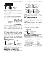
2.9
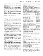
Fire Zone Wiring
4-Wire Smoke Detectors
All fire zones must be wired according to the following diagram:
2-Wire Smoke Detectors (50/300 only)
If PGM2 has been programmed for a 2-wire smoke detector
connection, the detectors must be wired according to the fol-
lowing diagram: