8
8. PROBLEMS AND SOLUTIONS
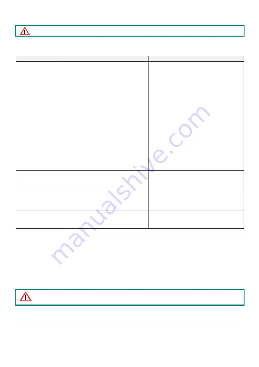
A diagnostics table is provided below that indicates the main anomalies, the probable causes and the possible solutions.
If you were not able to solve the problem after consulting the diagnostics table, do not try to find the fault by disassembling
machine parts but contact the Dropsa technical office and report the discovered anomalies, with a detailed description.
PROBLEM
POSSIBLE CAUSE
REMEDIAL ACTION
The electric pump is not
delivering any lubricant.
The electric motor is not functioning.
The tank is empty.
The pump is not triggered. Causes of the pump’s
failure to trigger:
•
The motor is turning in an inverted direction
(clockwise);
•
The motor is turning in the right direction but the
stirring paddle is not turning;
•
Presence of air bubbles in the lubricant.
The pressure adjustment valve (bypass) has been
calibrated at too low a value
Presence of dirt in the non-return valve.
Check the connection between motor and electric supply
line.
Check the motor winding.
Check that the connection plates for the motor terminal
box are positioned in accordance with the supply voltage.
Fill the tank.
N.B.: If the tank was emptied without the electric signal
for reaching the minimum level being given, the minimum
level contact must be checked.
Remove the cover from the tank and check that the
stirring paddle is turning anticlockwise and that the
lubricant is moving; if not invert two of the three motor
phases.
See above.
Remove the pump delivery pipe and drain off the
lubricant until the air bubbles have been eliminated.
The pump will not go
under pressure.
Possible dirt on the cone of the pump stop valve
Clean the cone and the pumping element stop valve
housing, draining off the lubricant.
Replace the gasket (code 3190489).
No signal indicating
minimum level when
there is no lubricant in
the tank.
Incorrect adjustment of minimum level.
Check the correct functioning of the level probe in the
following way:
Dismantle the minimum level unit and recalibrate the
capacitive probe.
Selection of minimum
level, with lubricant
below the minimum and
pump working.
Incorrect adjustment of minimum level.
The light on the control panel is still on: check the electric
connection and, if necessary, replace the capacitive
probe.
9. MAINTENANCE PROCEDURE
The pump was designed and built in order to minimise maintenance requirements.
To simplify maintenance, it is recommended to install it in an easy to reach position.
•
Periodically check the pipe joints to detect any leaks. Furthermore, always keep the pump clean to be able to quickly detect
any leaks or defects.
•
Check if the loading filter is clean after every 2000 hours of operation.
The machine does not require any special equipment for any control and/or maintenance activity. It is recommended to use
tools and personal protective devices suitable for use (gloves) and that are in good condition according to current regulations to
prevent damage to people or machine parts.
In the case of doubts and/or problems that cannot be solved, do not try to discover the reason by disassembling machine parts,
but contact the DROPSA S.p.A technical office.
10. DISPOSAL
During maintenance or disposal of the machine care should be taken to properly dispose of environmentally sensitive items such
as oils or other lubricants. Refer to local regulations in force in your area. When disposing of this unit, it is important to ensure
that the identification label and all the other relative documents are also destroyed.
ATTENTION
: The unit may only be opened and repaired by authorised Dropsa personnel.
ATTENTION
:
Make sure that the electric and hydraulic power supplies are disconnected before carrying out any
maintenance work.


