


Manual, Ultra High Sensitivity Aerosol Spectrometer (UHSAS)
DOC-0210 Rev E-4
3 2
© 2017 DROPLET MEASUREMENT TECHNOLOGIES
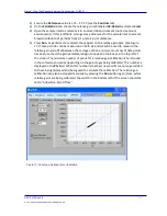
11)
Repeat for as many particles as needed.
Changes to the calibration curve will take effect on the next bin map commit. For more detailed
information on the calibration tab, see section 13.0.
5.3 Calibration Confirmation
5.3.1
Particle Size Calibration Confirmation
In order to confirm calibration of the UHSAS instrument, the following steps should be taken.
1)
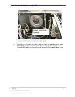
Confirm that the laser reference level and scattering level are at their original values. If
they are not, cleaning may be needed; see section 7.0.
2)
Run a monodisperse sample of PSL particles to the instrument sample inlet. These
should be PSL standard reference materials from NIST—the NIST 100 nm SRM or the
NIST 269 nm SRM. Other manufacturers’ particles may not agree with the sizes reported
by NIST, and therefore cannot be used to confirm the factory calibration with a high
degree of accuracy.
3)
Configure a size bin map around the particle size used. A good choice is a bin map with
99 bins, a start value of 0.5 times the nominal size, and a stop value of 1.5 times the
nominal size.
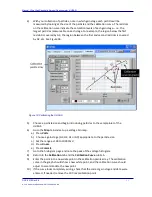
4)
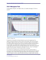
Start a histogram.
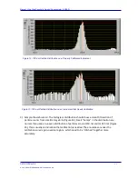
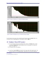
5)
Accumulate a sufficient number of counts and confirm that the peak position is in
agreement with the known particle size. If it is not, recalibration may be needed.
5.3.2
Flow Rate Calibration Confirmation
UHSAS users should periodically confirm that the sample flow is properly calibrated. To do this,
follow the steps below.
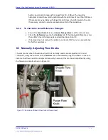
1)
Set the sheath flow (700 ccm at sea-level) with the manual valve.
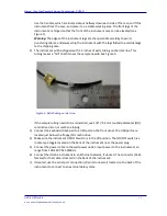
2)
Place a calibrated flow meter in line with the sample inlet.
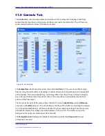
3)
Compare the results of the flow meter reading to the sample flow monitor on the
Controls
tab. The readings should be very similar.
If the flow meter and
Controls
tab reading differ considerably, the instrument may have a leak.
Check to ensure that all tubing is undamaged and tightly connected.
Note:
On the
Configuration
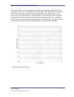
tab, the sample flow and sample set parameters are used to
convert mass flow signals into flow rates. The parameters are fits to 3
rd
order polynomials used


