background image

 7

Pressure Regulator Setting

The pressure regulator is usually delivered 

already set to the specifications indicated in 

the order sheet 
Whenever the set pressure must be 

modified, this value must be set within the 

setting range 

W

ds of the spring installed 

Make sure there is a flow demand or open 

the vent valve downstream of the regulator  

The vent valve should be closed after the 

desired set pressure is obtained 
•  

To increase the set pressure:

 rotate the 

adjustment screw (a) clockwise - see Fig 2 

Relatching the SSV -


see Fig 3

The safety shut-off valve must be re-latch 

only after verifying the reasons for the SSV 

to trip and after having re-establish normal 

operating conditions 
Before re-latching the safety slam-shut 

valve, make sure that the downstream valve 

is closed
•  

a

 - unscrew cover (bb) to remove it; 

•  

b

 - screw it upside down on the stem 

(aa) until it comes into contact with the 

controller top casing; continue to screw it 

slowly, this causes the valve to open gently 

and the pressure to fill the downstream 

pipe  

On RB 1800 / RB 1800F - this causes the 

internal by-pass to open  When the outlet 

pressure has stabilized,
•  

c

 - pull the stem and cover outwards to re-

latch the trip mechanism  The stem shall 

remain in ãopen“ position;

•  

d

 - unscrew the cover and 

replace it in 

operation position

 on the controller top 

casing 

Setting the SSV

The safety slam-shut valve is usually delivered 

already set to the specifications indicated in 

the order sheet  
Whenever the set value of the trip pressure 

p

dso for over-pressure (and/or 

p

dsu for 

under-pressure must be modified, this value 

must be set within the set range 

W

dso (and/

or 

W

dsu) of the spring installed 

Do not modify the set value when the SSV 

controller is not under pressure 
•  To increase the set value: rotate clockwise 

the adjustment screw (b) for upper trip 

pressure or the adjustment screw (c) for 

lower trip pressure - 

see Fig 2.

Summary of Contents for RB 1700

Page 1: ...Gas Regulators Gas Pressure Regulator RB 1700 RB 1800 RB 1800F 3170992801 AD Installation and starting up Installatione e messa in servizio Installation et mise en service Instalaciôn y pustea en Marcha ...

Page 2: ...2 ...

Page 3: ...ting of regulator and SSV 22 23 IT Instruction of installation Regulator start and set up Sensing line 12 Re latching SSV set up SSV 13 Connection of breathing line table 20 Example of installation 21 Adjusting of regulator and SSV 22 23 FR Instruction of installation Regulator start and set up Sensing line 15 Re latching SSV set up SSV 16 Connection of breathing line table 20 Example of installat...

Page 4: ...e 13 Applied conformity assessment procedures PED Module D1 Applied harmonized standards DIN EN 334 2005 A1 2009 and DIN EN 14382 2005 A1 2009 AC 2009 Other applied EC Directives 2014 30 EU electromagnetic tolerance only for optional electronic device Engaged notified body Module D Surveillance of the QS System TÜV SÜD Industrie Service GmbH Westendstraße 199 D 80686 München Examination inspection...

Page 5: ...e must be done by trained or qualified personal Afterwards a tightness test with 1 1 x PS must be per formed When changing pressure contain ing parts their compliance with the PED must be assured If used with wet gas internal and external effect of corrosion has to be checked reg ularly and in case of severe corrosion the product has to be replaced Please don t use solvent or alcohol contain ing p...

Page 6: ...n Regulator Start up Before start up the installation must be checked for leaks To start up the regulator properly proceed as follows check that the upstream and downstream on off valves and the vent valve are all closed partially open the upstream on off valve slowly enough to pass a very small amount of gas reset the safety shutoff valve See Relatching the SSV Notethatasafetyshutoffvalvewithover...

Page 7: ...n on the stem aa until it comes into contact with the controller top casing continue to screw it slowly this causes the valve to open gently and the pressure to fill the downstream pipe On RB 1800 RB 1800F this causes the internal by pass to open When the outlet pressure has stabilized c pull the stem and cover outwards to re latch the trip mechanism The stem shall remain in ãopen position d unscr...

Page 8: ...a conformidad PED Modulo D1 Norma técnica aplicada DIN EN 334 2005 A1 2009 y DIN EN 14382 2005 A1 2009 AC 2009 Otra directiva EC aplicada 2014 30 UE compatibilidad electromagnética únicamente para equipamiento electrónico complementario El organismo notificado Módulo D Aseguramiento de la calidad TÜV SÜD Industrie Service GmbH Westendstraße 199 D 80686 München Verificación inspecciones controles d...

Page 9: ... de instalaciôn Puesta en marcha del regulador Antes de la puesta en marcha de la instalaciôn se debe comprobar que no hay fugas Para la puesta en marcha del regulador correctamente se ha de proceder de la forma siguiente Comprobar que las válvulas on off aguas arriba y aguas abajo y la válvula de escape están todas cerradas Abrir lentamente la válvula on off aguas arribadejandopasarunapeque acant...

Page 10: ...asta que haga contacto con la cubierta de la tapa del regulador continúe atornillándolo lentamente esto hace que la válvula se abra suavemente y la tubería se presurice aguas abajo En el RB 1800 RB 1800F Esto hace que el by pass interno se abra cuando la presiôn de salida está estabilizada c Tirar del vástago hacia fuera para volver a enganchar el mecanismo de rearme El vástago permanecerá en la p...

Page 11: ...lo 13 Valutazione delle conformità applicate PED Modulo D1 Norme e standard tecnici applicati DIN EN 334 2005 A1 2009 e DIN EN 14382 2005 A1 2009 AC 2009 Altre Direttive CE applicate 2014 30 UE tolleranze elettromagnetiche solo per i dispositivi elettronici opzionali Organismo Notificato Il Modulo D è supervisionato da TÜV SÜD Industrie Service GmbH Westendstraße 199 D 80686 München Esami inspezio...

Page 12: ...della messa in esercizio è necessario assicurarsi che l installazione non presenti perdite Al fine di mettere in esercizio correttamente il regolatore procedere come di seguito descritto controllare che le valvole di intercettazione di monte e valle e che la valvola di spurgo siano chiuse Aprire parzialmente la valvola di monte affinché possa passare una piccola quantità di gas Armare la valvola d...

Page 13: ...re il tappo bb e rimuoverlo b avvitarlo al contrario sull albero aa fino al contatto col coperchio del pressostato continuare ad avvitare lentamente questo genera un apertura graduale della valvola e l invasodellatubazionedivalle Sulmodello RB 1800 Direxi 1800 questo genera altresì l apertura di un by pass interno Quando la pressione di valle si è stabilizzata c tirare l albero ed il coperchio ver...

Page 14: ...a conformité PED Module D1 Norme technique appliqué DIN EN 334 2005 A1 2009 et DIN EN 14382 2005 A1 2009 AC 2009 autre directive EC appliqué 2014 30 UE compatibilité électromagnétique uniquement pour d équipement électrique complémentaire L organisme notifié Module D Surveillance du system qualité TÜV SÜD Industrie Service GmbH Westendstraße 199 D 80686 München Vérification surveillance contrôle d...

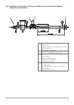
Page 15: ...quiper la ligne d impulsion du clapet de sécurité d un robinet d isolement La Fig 1 montre un schéma typique d installation Mise en service du détendeur Vérifier l étanchéité de l installation avant mise en service Pour la mise en service du détendeur s assurer que les vannes amont et aval ainsi que le robinet de fuite sont fermés Ouvrir lentement et partiellement la vanne amont Réarmer le clapet ...

Page 16: ...coquille supérieure continuer à visser lentement pour ouvrir le clapet et remplir le volume aval du détendeur RB 1800 RB 1800F cette opération ouvre le bipasse interne c Après stabilisation de la pression aval tirer le bouchon et la tige pour réarmer la tige de clapet doit rester en position ouverte d dévisser le bouchon et revisser le en position normale sur la coquille de l actionneur Réglage du...

Page 17: ...Modul D1 Angewandte harmonisierte Normen DIN EN 334 2005 A1 2009 und DIN EN 14382 2005 A1 2009 AC 2009 Weitere angewandte EU Richtlinien 2014 30 EU elektromagnetische Verträglichkeit nur für zusätzliche elektrische Einrichtungen Eingeschaltete notifizierte Stellen Modul D Überwachung QS System TÜV SÜD Industrie Service GmbH Westendstraße 199 D 80686 München Prüfung Überwachung Kontrollen während d...

Page 18: ...iebnahme Nach Einbau des Regelgerätes in die Regel anlage ist die Dichtheit der Anlage zu über prüfen Das Absperrventil auf der Ein und Ausgangsseite ist zu schließen Absperrventil auf der Eingangsseite lang sam und vollständig öffnen SAV langsam öffnen bis es in Offenstel lung bleibt und sich Schließdruck bei dem Regler einstellt siehe auch Seite xx Absperrventil auf der Ausgangssei te langsam un...

Page 19: ...inde der herausstehenden Ventilstan ge aa aufschrauben bis sie den Feder dom des Membran Gehäuses berührt 2 durch weiteres langsames Hinein schrauben öffnet das SAV Gas strömt über das Regelgerät in die Ausgangssei te der Regelanlage Es stellt sich Schließ druck ein 3 Herausziehen der Ventilstange bis das Sicherheitsabsperrventil in der Offenstel lung einrastet 4 Verschlusskappe von Ventilstange e...

Page 20: ...1722 1830 1831 1832 1820 1821 1822 1810 1 811 1812 RB 1700 Ø 2mm Ø 2mm G 1 2 1 G 1 2 1 RB 1700 1 G 3 4 G 3 4 RB 1800 1 G 3 4 G 3 4 G 3 4 SSV 1721 1722 1731 1732 1831 1832 1821 1822 1811 1812 RB 1700 Ø 2mm Rp 1 8 1 RB 1700 1 Ø 2mm Rp 1 8 1 RB 1800 1 Rp 1 8 Rp 1 8 Rp 1 8 Rp 1 8 1 optional ...

Page 21: ...a de instalaciôn 1 5 13 14 1 Inlet valve Valvola di intercettazione di monte Vanne amont Válvula de máxima 5 RB 1700 RB 1800 RB 1800F 13 Vent valve Robinetto di sfiato Event du régulateur Válvula de escape 14 Outlet valve Valvola di intercettazione di valle Vanne aval Válvula de mínima ...

Page 22: ...iôn a b Fig 2 a Regulator Regolatore Régulateur Regulador Fig 2 b SSV Fig 2 c d Over and under pressure shut off valve Dispositivo di blocco per maxima e minima pres sione Clapetdesécuritéàmaxietmini de pression Dispositivo de seguridad por máxima y mínima presiôn c d ...

Page 23: ...ation non ATEX Puissance de commutation Contact power rating Max 10 W Max 120 mW Rigidité diélectrique entre contacts ouverts Voltage Break down Max 180 Vdc Max 15 Vdc Courant de commutation Current Switching Max 50 mA Max 50 mA Capacité et inductance Capacitance and Inductance C 0F L 0H C 0F L 0H Température de fonctionnement Operation temperature range 25 C to 55 C 25 C to 55 C Le détecteur est ...

Page 24: ...th America LLC All rights reserved Dresser Utility Solutions reserves the right to make changes in specifications and features shown herein or discontinue the product described at any time without notice or obligation Contact your Dresser Utility Solutions representative for the most current information The Dresser Logo and all Trademarks containing the term Dresser are the property of Dresser LLC...

Reviews: