Flowgrid Slam Shut | 15
Assembly of the Shut-off Valve
Refer to Figure 11 for this operation.
1. Install the (two) shaft bushings into the valve housing.
Align the cutaway section of the bushing toward center
wall of the housing so the bushing shoulder sits against
the housing wall
2. Hold the flapper so the lugs are down and slide them
between the two bushings just installed. Slide the shaft
into the valve housing, through the bushing and the first
lug on the flapper.
3. Place the left flapper spring between flapper lugs. The
straight spring leg should be against the bushing and the
center wall of the housing. The bent spring leg should be
against the back side of the flapper in the center. Slide
the shaft through the spring. Repeat the process for the
right flapper spring. Slide the shaft through the second
lug in the flapper and into the second bushing.
4. Have a second person hold the top face of the flapper
flush with the top of the valve body. Align the shaft so
the two pin holes align with the pin holes in the flapper.
Install the two split pins using a pin punch larger than the
pin hole in the flapper. Drive the top of the pins flush with
the top of the flapper surface when the flapper is pushed
down.
5. Lube the o-rings with lubricant supplied in the rebuild kit.
6. Install the appropriate o-ring on the rear reset nut. Screw
the nut on the end of the shaft.
7. Install the flapper seal into the seal retainer making sure it
is seated in the groove.
8. Using a 1/2 inch or 13 MM wrench turn the shaft clock-
wise so the top of the flapper is flush or below the top of
the valve housing.
9. Install the seal retainer with the flapper seal down onto
the slam shut body. The small flow hole in the seal goes
on the flapper side of the slam shut body. Install two flat
head screws through the seal retainer and into the slam
shut body using a hex wrench. Make sure the screws are
tightened eliminating the gap between the slam shut body
and the seal retainer. Insure the tops of the screw are
below the surface of the seal retainer.
10. Slide the o-ring onto the flapper shaft. Being careful not to
damage the o-ring install it into the bore in the slam shut
body.
11. Install the o-rings on the bushing. Slide the bushing
onto the shaft and push it into the slam shut body as far
it will go.
CAUTION
Do not damage the sealing bead on the flapper or the
shut-off valve will leak. If the pins stick up above the
flapper they will cut the seal and cause the shut-off
valve to leak.
Assembly of the Shut-off Valve onto the Body and/or
Regulator
Refer to Figure 10 for this operation.
1. Install the body seal in the Flowgrid body.
2. Slide the slam shut valve assembly over the studs and
onto the Flowgrid body.
3. If the slam shut valve is integrated into a Flowgrid
regulator, assemble the Flowgrid regulator according to
the instructions in the Flowgrid IOM manual in the same
orientation it was removed.
4. If the slam shut is not integrated into a Flowgrid regulator
then install the o-ring and cap on top of the shut off valve
assembly.
5. Install and tighten the four nuts. Torque 2” valves to 65
ft-lbs, 3” and 4” valves to 125 ft-lbs.
Installation of the Controller onto the Shut-off Valve.
Refer to Figure 9 for this operation.
NOTE: With the controller removed the maintenance on
the controller now or later with the unit installed.
1. Lubricated the o-rings with the lubricant supplied in the
rebuild kit.
2. Install the o-rings in the proper grooves in the controller
and latch module where it mates with the shut-off valve
body..
3. Being careful to keep the o-rings in the grooves slide the
controller and latch module over the end of the shaft and
bushing onto the slam shut body. Align the bolt holes,
install and tighten the three bolts.
4. Slide the washer, pawl lever, bushing, pawl spring, and
washer on the stud. Install the spring with the bent leg of
the spring between the two legs of the “L” shaped Pawl
Lever.
5. Install and tighten the nut, enough to remove the slack in
the assembly. Be careful not to over tighten and damage
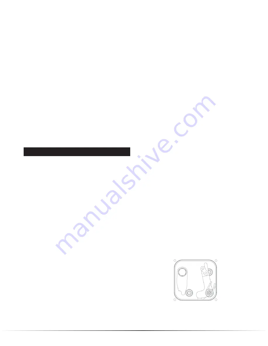
the threads. Using a pair of plyers, lift the bent end of
the spring over the Pawl lever into the position shown in
Figure 12.
6. Install the flapper lever so the end of the lever is pointing
down. Install the o-ring on the front reset nut. Install and
tighten the left hand threaded front reset nut on the shaft.
7. Position the cover o-ring on the cover and install the cover
on the front of the lever cavity. Install and tighten the four
cover screws.
Figure 12 - Final spring leg position.


