


Supplement operating manual for DREHMO i-Matic actuators with integrated
MODBUS fieldbus interface
Wenden, 21.03.12
Page 6 of 18
Prepared by: Ste
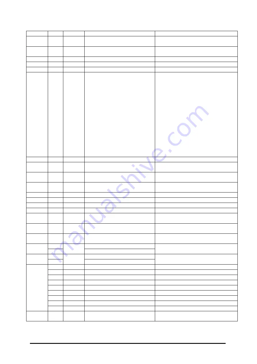
Register Bit
Coil
Signal
Meaning
0x204
0
49
Torque warning OPEN
Torque higher than torque warning level
set
1
50
Torque warning CLOSED
Torque higher than torque warning level
set
2
51
No signal of reference value
If imxx5, message if no reference value
3
52
Hardware fault
Warning message
4
53
Combined sensor defective
Warning message
5
54
system check error
During self-check the electronic unit has
detected an error. The unit then performs
a reset and tries to enter the state fail-
safe. The indication can be cleared by
using the acyclic bit „Reset system test
error“ in slot 1 index 240, or by using the
local reset in system>reset, or by a
power off on cycle. The kind of error
(refer to operating manual of
i-matic
) can
be read out by using the acyclic service
“system test error code” in slot 1 index
195 or the system entry under actual
value diagnosis on the local control
station. This indication is important for
safety related systems, if due to an error
the system needs to be brought to a safe
state.
6
55
Maintenance required
Perm. operating data are exceeded
7
56
Actuator is served
Logged in user is specialist or
manufacturer for service reasons
8
57
Regulating time too long
Regulating time longer than max. running
time
9
58
Max. valve stroke exceeded
Regulating distance longer than stroke of
valves
10
59
Hand wheel operation
Actuators hand wheel is in usage
11
60
Rotation monitor
Set if rotation direction is wrong
12
61
Data exchange channel 1
Data exchange on channel 1 active
13
62
Data exchange channel 2
Data exchange on channel 2 active
14
63
Channel 1 primary
Channel 1 commands are in use due to
highest channel priority
15
64
Channel 2 primary
Channel 2 commands are in use due to
highest channel priority
0x205
0..15
65..80
Torque value
0...1000ppt of the torque value at power
output
0x206
0..7
81..96
Position value low byte
0...1000ppt of analogue input 1
8..15
Position value high byte
0x207
0..7
97..112
Position value low byte
0...1000ppt of analogue input 2
8..15
Position value high byte
0x208
0
113
Process input 1
State of digital input 1
1
114
Process input 2
State of digital input 2
2
115
Process input 3
State of digital input 3
3
116
Process input 4
State of digital input 4
4
117
5
118
6
119
7
120
8..15
121..128
0x209..
0x220
129..512
In order to access the feedback signals, the function codes FC 05 (Force Single Coil) or FC 06 (Preset Single
Register) have to be used. The following tables give telegram examples for these function codes.


