12
8. PREPARING THE COMPRESSOR
NOTE:
Remove the plug from the socket before carrying
out adjustment, servicing or maintenance.
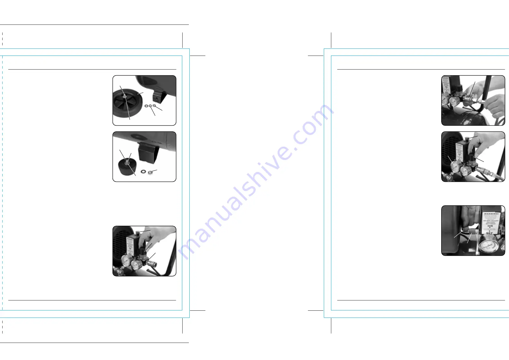
8.1 LOCATION AND ASSEMBLY - FIGS. 1-2
It is extremely important to install the compressor in a
clean, well ventilated area where the surrounding air
temperature will not be more than 40ºC. A minimum
clearance of 500mm between the compressor and a wall
is required.
Fitting the wheels (fig.1):
Pass the bolt
through the wheel
and then
place on the first washer
, then the spacer
.
Fit the wheel through the wheel bracket on the
underside of the compressor’s frame then fit the second
washer before finally securing with the nut
.
Fitting the rubber anti-vibration foot (fig.2):
Pass the bolt
through the rubber foot
and
place on the first washer
.
Pass the bolt through the
foot bracket on the bottom of the tank then fit the
second washer before finally securing with the nut
.
Fitting the air filter:
Remove the transit bung from the top of the head and
screw the air filter
into the filter connection.
Fitting the oil plug:
Remove the transit bung from the oil inlet. Check oil
level is correct then screw in the supplied oil plug
.
In addition to pneumatic air tools, your compressor may be connected to several accessories
suitable for blowing, washing and spraying. For technical specifications and detailed
instructions, please refer to the instructions provided for the individual accessory.
When the installation procedure is complete, the compressor is ready for use.
Make sure the
pressure switch button
is positioned "OFF".
Switch the pressure switch button to the "ON" position to start the compressor.
8.2 INITIAL STARTUP – FIG. 3
– Insert a euro connector into the air outlet connector
and open the regulator fully.
– Turn the compressor on by pulling the pressure
switch On/Off
button up.
– Run the compressor for 30 minutes allowing the
pressure to escape.
– Turn the regulator dial
fully counter-clockwise
allowing pressure to build up. Once the maximum
pressure is reached, the pressure switch will
automatically turn the machine off.
– Turn the compressor off, by pressing the pressure
switch On/Off button down and open the regulator
valve allowing the air to escape.
11
9. OPERATION
9.1 BASIC COMPRESSOR OPERATION
– FIGS. 4-5
– Connect the air line to the compressor by pulling
back the collar
on the air outlet quick coupling
and inserting the corresponding air coupling
fitted on the air line. Release the collar so it slides
back in place to secure the air coupling.
– Turn the air regulator
clockwise to its lowest
setting and turn on the compressor by lifting the
pressure switch On/Off button
upwards.
– Once the compressor has reached maximum
pressure, open the regulator valve
to the desired
pressure on the air outlet regulator gauge
.
9.2 MOISTURE IN COMPRESSED AIR
Moisture in compressed air will form into droplets as it
comes from an air compressor pump. When humidity is
high or when a compressor is in continuous use for an
extended period of time, this moisture will collect in
the tank. When using a paint spray gun or sandblast
gun, this water will be carried from the tank through
the hose, and out of the gun as droplets mixed with the
spray material.
IMPORTANT:
This condensation will cause water spots in
a paint job, especially when spraying other than water
based paints. If sandblasting, it will cause the sand to
case and clog the gun rendering it ineffective. A filter in
the air line, located as near to the gun as possible, will
help eliminate this moisture.
9.3 SAFETY VALVE – FIG. 6
WARNING:
DO NOT REMOVE OR ATTEMPT TO ADJUST
THE SAFETY VALVE!
This valve
should be checked under pressure
occasionally by pulling the ring
by hand. If air
leaks after the ring has been released, or valve is stuck,
it
MUST
be replaced.
FIG.1
FIG.2
FIG.3
FIG.4
FIG.5
FIG.6


