background image

2. CONTENTS

3

2.1 CONTENTS

PAGE CONTENT


PAGE

1 TITLE 

PAGE


1.1 

INTRODUCTION 

............................................................................................... 2


1.2 

REVISION 

HISTORY........................................................................................... 2


1.3 

UNDERSTANDING THIS MANUAL ................................................................... 2


1.4 

COPYRIGHT 

NOTICE ......................................................................................... 2

2 CONTENTS
  

2.1 

CONTENTS ........................................................................................................ 3

3 GUARANTEE
  

3.1 

GUARANTEE ..................................................................................................... 4

4 INTRODUCTION
  

4.1 

SCOPE 

............................................................................................................... 5


4.2 

SPECIFICATION ................................................................................................. 5


4.3 

HANDLING & STORAGE ................................................................................... 5

HEALTH & SAFETY INFORMATION


5.1 

GENERAL  SAFETY INSTRUCTIONS FOR POWER TOOL USE ........................... 6


5.2 

ADDITIONAL SAFETY INSTRUCTIONS FOR SAFETY VALVES .......................... 8


5.3 

ADDITIONAL SAFETY INSTRUCTIONS FOR PRESSURE VESSELS...................... 9A


5.4 

CONNECTION TO THE POWER SUPPLY ........................................................... 9A

6 TECHNICAL 

DESCRIPTION


6.1 

IDENTIFICATION ............................................................................................... 10B

UNPACKING & CHECKING


7.1 

PACKAGING...................................................................................................... 10A


7.2 

WHAT’S IN THE BOX ........................................................................................ 10A

PREPARING THE COMPRESSOR


8.1 

LOCATION AND ASSEMBLY............................................................................. 11


8.2 

INITIAL 

STARTUP .............................................................................................. 11

9 OPERATION


9.1 

BASIC COMPRESSOR OPERATION ................................................................... 12


9.2 

MOISTURE IN COMPRESSED AIR ..................................................................... 12


9.3 

SAFETY 

VALVE.................................................................................................. 12


9.4 

THERMAL OVERLOAD PROTECTOR ................................................................ 13


9.5 

STORAGE .......................................................................................................... 13

10 TROUBLESHOOTING........................................................................................................... 14
11 MAINTENANCE ................................................................................................................... 15


11.1 

BASIC MAINTENANCE AND CHECKS ............................................................... 15


11.2 

GENERAL MAINTENANCE AND SERVICE INTERVALS ..................................... 16

12 

EXPLANATION OF SYMBOLS


12.1 

EXPLANATION OF SYMBOLS ........................................................................... 17

13 DISPOSAL
  

13.1 

DISPOSAL 

......................................................................................................... 18

14 GLOSSARY
  

14.1 

GLOSSARY 

....................................................................................................... 18

DECLARATION OF CONFORMITY .....................................................................................ENCLOSED

Summary of Contents for Stormforce DA50/207/BK

Page 1: ...is manual has been compiled by Draper Tools describing the purpose for which the product has been designed and contains all the necessary information to ensure its correct and safe use By following all the general safety instructions contained in this manual it will ensure both product and operator safety together with longer life of the product itself AlI photographs and drawings in this manual a...

Page 2: ...3 1YFUK 1 3 UNDERSTANDING THIS MANUALS SAFETY CONTENT WARNING Information that draws attention to the risk of injury or death CAUTION Information that draws attention to the risk of damage to the product or surroundings 1 4 COPYRIGHT NOTICE Copyright Draper Tools Limited Permission is granted to reproduce this publication for personal educational use only Commercial copying redistribution hiring o...

Page 3: ...ESSELS 9A 5 4 CONNECTION TO THE POWER SUPPLY 9A 6 TECHNICAL DESCRIPTION 6 1 IDENTIFICATION 10B 7 UNPACKING CHECKING 7 1 PACKAGING 10A 7 2 WHAT S IN THE BOX 10A 8 PREPARING THE COMPRESSOR 8 1 LOCATION AND ASSEMBLY 11 8 2 INITIAL STARTUP 11 9 OPERATION 9 1 BASIC COMPRESSOR OPERATION 12 9 2 MOISTURE IN COMPRESSED AIR 12 9 3 SAFETY VALVE 12 9 4 THERMAL OVERLOAD PROTECTOR 13 9 5 STORAGE 13 10 TROUBLESH...

Page 4: ...hase except where tools are hired out when the guarantee period is ninety days from the date of purchase This guarantee does not apply to normal wear and tear nor does it cover any damage caused by misuse careless or unsafe handling alterations accidents or repairs attempted or made by any personnel other than the authorised Draper warranty repair agent Note If the tool is found not to be within t...

Page 5: ...per minute no load 2 850min 1 Maximum working pressure 116psi 8bar Air displacement 7 3cfm 206L min Free air delivery 4cfm 113L min Receiver capacity 50 Litres Sound power level 97dB A Sound pressure level 71 4dB A Single value noise level 93 0dB A Dimensions LxWxH 765x325x705mm Weight 33kg 4 3 HANDLING STORAGE This compressor is designed to be moved to different locations Ensure it is always oper...

Page 6: ...d contact with earthed surfaces because they can conduct electricity if there is an electrical fault with the power tool Always protect the power cable and route it away from danger Keep bystanders away Children onlookers and passers by must be restricted from entering the work area for their own protection The barrier must extend a suitable distance from the tool user Unplug and house all power t...

Page 7: ...applicable keep blades sharp moving parts clean oiled or greased handles clean and emergency devices working Wait for the machine to stop Unless the machine is fitted with a safety brake some parts may continue to move due to momentum Wait for all parts to stop then unplug it from the power supply before making any adjustments carrying out maintenance operations or just finishing using the tool Re...

Page 8: ...o persons and or things The valve rod must therefore be free in its movement when discharging The connection between the valve and the part to be protected must be free from all kinds of choking and be as short as possible so as not to reduce the discharge flow rate of the valve itself The connection passage area must be greater than the valve orifice area During installation screw on the valve wi...

Page 9: ...ation in force in the country in which the tank is operated The construction is mainly effected for permanent load by internal pressure Cyclic loads are not considered only for a range of 10 PS 5 4 CONNECTION TO THE POWER SUPPLY Make sure the power supply information on the machine s rating plate are compatible with the power supply you intend to connect it to This compressor comes supplied with a...

Page 10: ...ation in force in the country in which the tank is operated The construction is mainly effected for permanent load by internal pressure Cyclic loads are not considered only for a range of 10 PS 5 4 CONNECTION TO THE POWER SUPPLY Make sure the power supply information on the machine s rating plate are compatible with the power supply you intend to connect it to This compressor comes supplied with a...

Page 11: ...line the telephone number appears on the Title page and do not attempt to use the compressor The packaging material should be retained at least during the guarantee period in case the machine needs to be returned for repair Warning Some of the packaging materials used may be harmful to children Do not leave any of these materials in the reach of children If any of the packaging is to be thrown awa...

Page 12: ...line the telephone number appears on the Title page and do not attempt to use the compressor The packaging material should be retained at least during the guarantee period in case the machine needs to be returned for repair Warning Some of the packaging materials used may be harmful to children Do not leave any of these materials in the reach of children If any of the packaging is to be thrown awa...

Page 13: ...Off button up Run the compressor for 30 minutes allowing the pressure to escape Turn the regulator dial fully counter clockwise allowing pressure to build up Once the maximum pressure is reached the pressure switch will automatically turn the machine off Turn the compressor off by pressing the pressure switch On Off button down and open the regulator valve allowing the air to escape 11 9 OPERATION...

Page 14: ...Off button up Run the compressor for 30 minutes allowing the pressure to escape Turn the regulator dial fully counter clockwise allowing pressure to build up Once the maximum pressure is reached the pressure switch will automatically turn the machine off Turn the compressor off by pressing the pressure switch On Off button down and open the regulator valve allowing the air to escape 11 9 OPERATION...

Page 15: ... causes Low voltage Clogged air filter Lack of proper ventilation CAUTION IF THE THERMAL OVERLOAD PROTECTOR IS ACTUATED THE MOTOR MUST BE ALLOWED TO COOL DOWN BEFORE START UP IS POSSIBLE THE MOTOR WILL AUTOMATICALLY RESTART WITHOUT WARNING IF LEFT PLUGGED INTO ELECTRICAL OUTLET AND UNIT IS TURNED ON 9 5 STORAGE When not in use store hose and compressor in a cool dry place Drain tank of moisture Di...

Page 16: ...too slow 2 Air filter choked up 3 Leakage of safety valve 4 Leakage of discharge pipe 5 Sealing gasket damaged 6 Valve plate damaged carbon buildup or stuck 7 Piston ring and cylinder worn or damaged 1 Oil level too high 2 Breather pipe blockage 3 Piston ring and cylinder worn or damaged 1 Check the power supply 2 Replace the wire 3 Repair or replace 4 Repair or replace 5 Check and repair Check cr...

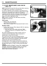
Page 17: ... Monthly checks Remove the foam air filter element for cleaning or renew if necessary Rinse the filter with water and soap Make certain the element is completely dry prior to re fitting The cleaning replacement of the air filter must be carried out more frequently if the compressor is operating in a dusty environment The motor must be correctly ventilated during operation For this reason avoid blo...

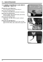
Page 18: ...eck the oil level and replensish if necessary After every 50 working hours Ensure all fixings have remained tight particularly on the head and crankcase After every 60 working hours Open drain cock under the tank to exhaust condensate After every 120 working hours Clean crankcase and renew the oil clean air filter and check safety valve and pressure gauge after FIG 9 FIG 10 FIG 11 ...

Page 19: ...BOLS 12 1 EXPLANATION OF SYMBOLS Warning Wear dust mask Warning Wear goggles Warning Read the instruction manual Warning Wear ear defenders WEEE Do not dispose of Waste Electrical Electronic Equipment in with domestic rubbish ...

Page 20: ...posed of according to national regulations Contact your local authority for details of collection schemes in your area In all circumstances Do not dispose of power tools with domestic waste Do not incinerate Do not abandon in the environment Do not dispose of WEEE as unsorted municipal waste Waste Electrical Electronic Equipment ...

Page 21: ...way valve that allows air to enter the tank but prevents air in the tank from flowing back into the compressor pump Regulator The regulator controls the amount of air pressure released at the hose outlet Safety valve The valve automatically releases air if the tank pressure exceeds maximum pressure ...

Page 22: ...Desk 023 8049 4333 Internet www drapertools com E mail sales drapertools com Sales Fax 023 8049 4209 General Enquiries 023 8026 6355 Service Warranty Repair Agent For aftersales servicing or warranty repairs please contact the Draper Tools Helpline for details of an agent in your local area YOUR DRAPER STOCKIST RWCH150313 ...

Reviews: