Section 11 -
Electrical Connections
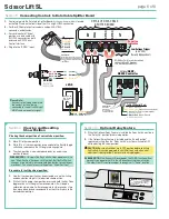
Lift operates on 115V, 60 Hz. current. 14 amps current draw
(2 amps
for lift, 12 amps for Outlet)
Lift ships with internal wiring complete and
control switch
(es)
fully boxed.
Wire to connect lift to switch
(es)
and switch
(es)
to power supply
should be furnished by installer.
Please Note:
Lift must be installed in accordance with
requirements of Local Building Codes, Canadian Electrical Code
(CEC)
, CAN/CSA C22.1 and National Electric Code
(NEC)
, NFPA
70. An appropriate disconnect device shall be provided as part of
building installation.
CAUTION:
All operating switches should be "off" before power
is connected.
Terminal strip for field connections is located inside a junction box
on the end of the unit. Unit ships with internal lift wiring complete to
terminal strip. Use switch to lower lift and remove packing. Remove
temporary wiring and complete permanent wiring to electricity and
to switches. Wire to connect unit to power supply and to switches
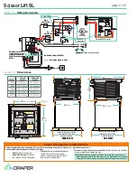
should be furnished by installer. Connections should be made
in accordance with wiring diagram. Lift should be operated and
checked prior to installing projector and/or optional ceiling closure.
Section 13 -
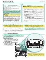
Testing Safety Limit Switches
CAUTION:
Lift is equipped with two Safety Limit Switches
(see "Adjustments")
.
This switch may be damaged during shipping or by rough handling on the
job site.
1.
After the Lift has been installed in the ceiling, but before the projector and
closure are attached, the Safety Limit must be tested.
2.
Use a screwdriver or other tool to hold down the Safety Limit Switch. While
holding down Safety Limit Switch, other installer should operate the unit. If
the unit works, Safety Limit Switch is broken and must be replaced.
CAUTION:
Operating the unit without a functioning Safety Limit Switch
could cause the unit's motor to continue operating after the lift is closed,
leading to a failure and the possibility of damage or injury.
Please Note:
As weight is applied to the Lift, the projector plate may shift
slightly. If this occurs, use set screws on bottom of fabric roller brackets to
compensate for shift and level projector plate.
Section 14 -
Adjusting Limit Switches
Caution:
The maintenance/service factory limit setting must
not be adjusted to a lower position than the preset factory limit
setting. In addition, Draper does not recommend setting show
position at the maintenance/service position.
PLEASE NOTE:
Changing the fully open or fully closed position will reset the
electronic controls and cause the lift to operate improperly. Please call Draper
before attempting these adjustments.
Adjusting FULLY DOWN position
1.
Limit switches for the Scissor Lift are preset at the
factory. The DOWN limit switch is set for the fully down
(maintenance)
position for the size lift you have ordered.
The limit switch assembly is located inside the lift and
behind the Lifting Cable Drum.
2.
The Down limit switches shown in the drawing are for
setting the "Fully Down" position.
This can be adjusted manually by
loosening or tightening the screw
to increase or reduce the travel.
DOWN
Limit
Switch
ROTATE
TO
ADJUST
DOWN
Section 12 -
Operation
CAUTION:
When operating for the first time, cycle unit down and up several
times to confirm satisfactory operation. Be prepared to cut POWER if
necessary.
• 110-120V SINGLE STATION CONTROL -
3-position UP-OFF-DOWN switch
permits operation to be stopped at any point. Factory adjusted limit switches
automatically stop screen when fully down or fully up.
• 24V CONTROL -
3-button UP-STOP-DOWN switches stop at any point desired
and operate in any sequence. Factory adjusted limit switches automatically
stop screen when fully up or fully down. Installer should incorporate an all-pole
disconnect in fixed wiring available with RF or IR remote.
• KEY OPERATED SWITCHING -
Two key-operated switches optionally
available with this unit:
•
Key-operated power supply switch controls power to screen and switches.
When "off", switches will not operate screen. Key may be removed from
switch in either "on" or "off" position.
•
Three-position key switch permits the screen to be operated directly by key.
Requires screen operator to have a key.
• RS232 / ETHERNET -
Serial communication and network communication
optionally available.
page 7 of 8
Scissor Lift SL


