Section 7 -
Channel Adaptors
(Optional)
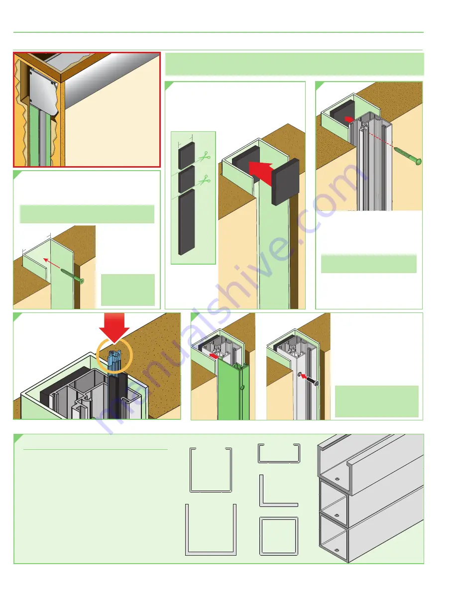
If the opening is not suitable for direct mounting either
component due to uneven surfaces, stonework, trim, or
other irregular element, use Channel Adaptors to build in
or fur out an opening to enable Side Channel or headbox
attachment.
Channel Adaptors can provide a mounting surface for both
the Side Channels and headbox. If necessary, installer can
"stack" a sufficient number of tubes to bring the opening
flush from floor to ceiling.
Use and configuration of Channel Adaptors is site
dependent: each installation may require different adaptors
or a combination of adaptors. Installer is responsible for
safely and securely attaching Channel Adaptors to prepare
each opening for best installation of the product.
STA
CKI
NG
CHA
NNE
L AD
APT
ORS
TO MO
DIF
Y SP
ACE
C073.002
C090.053
C104.148
C090.054
C
H
A
N
N
E
L
S
I
D
E
C
H
A
N
N
E
L
A
D
A
P
T
O
R
CE
ILI
NG
CEIL
ING
sha
de
W
A
L
L
END
CAP
HEADBO
X
W
A
L
L
W
A
L
L
CUT into
SQUARES
Foam
Padding
C054.2218
1.5"
(38mm)
W
A
L
L
W
A
L
L
Section 6 -
Mounting Side Channels Into a Recessed Pocket
(Optional)
W
A
L
L
W
A
L
L
si
de
ch
a
n
nel
cov
e
r
W
A
L
L
W
A
L
L
W
A
L
L
W
A
L
L
si
de
ch
a
n
nel
cov
e
r
W
A
L
L
W
A
L
L
5.
Re-attach the Side
Channel Cover and
secure with screws
removed in Section 5
(Installing Side Channels)
.
6.
Repeat Steps 1-5 at the
remaining Side Channel
mounting location.
Please Note:
Installer is
responsible for providing
space and clearance to mount
headbox above wall structure.
W
A
L
L
W
A
L
L
2"
(51mm)
1.
Insert provided 'U' Channel
(PN: C090.061)
into recessed cavity in building structure.
Secure the 'U' Channel using appropriate
hardware
(by others)
.
Please Note:
Installer is responsible for selecting
mounting hardware appropriate for site conditions.
2.
Cut foam strips
(provided)
into 1.5"
(38mm)
squares and attach them
to the 'U' Channel at all desired
mounting points of the Side Channel.
W
A
L
L
W
A
L
L
CUT into
SQUARES
Foam
Padding
C054.2218
1.5"
(38mm)
3.
Place the modified Side
Channel into the 'U' Channel
and secure it to the building
structure using appropriate
mounting hardware
(by others)
.
Please Note:
Max. spacing between
fasteners is 24"
(610mm)
.
Side Channel Mounting Hardware
(by others)
should go through center
of Foam Padding, through 'U'
Channel and then into the wall.
W
A
L
L
W
A
L
L
4.
Reinsert the Fabric
Retainer Strip.
Attach
Foam
Padding
at every
Side
Channel
Mounting
location.
NOTE:
Installer MUST provide a
recessed pocket at the top of
the channel large enough to
allow for headbox installation
and accommodate hem bar
and fascia install/removal.
Specific Fastener
locations are
determined by
installer.
Please Note:
Max. spacing
between fasteners
is 24"
(610mm)
.
PLEASE NOTE:
Channel Adaptor 2" U Channel option MUST be ordered for the
channel to be provided with unit — it is not provided standard.
C090.061
FlexShade
®
ZIP XL
page 6 of 11


