background image

Section 10 -

 Complete Electrical Connection

Operates on 110-120V, 60 Hz. current. Shade is shipped with internal wiring complete and control switch 

(es)

 fully boxed, and supplied with a 6' 

(183 cm)

 cable lead 

(standard)

. Longer lead can be substituted by removing two screws in motor end of roller, removing lead, plugging new lead in, and replacing screws. Wire to connect 

shade to switch 

(es)

 and switch 

(es)

 to power supply should be furnished by installer. Connections should be made in accordance with attached wiring diagram, and 

wiring should comply with national and local electrical codes.

DO NOT wire motors in parallel without written permission from Draper

®

.

 All operating switches should be “off” before power is connected.

Section 9 -

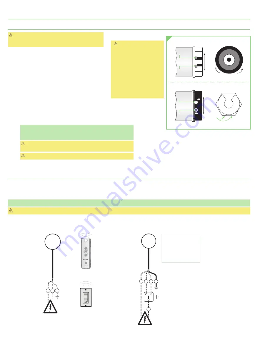
 Limit Setting: Standard and Quiet Motors

 Caution:

 Unit ships without limits. Limits will need to be set 

before the unit is operated. Always be prepared to shut off 

manually when new adjustment is being tested.

Push Button Limits

1. 

Fully depress both limit switch push buttons, then 

operate wall switch to make sure system works properly.

2. 

Raise shade to desired "UP" stop position.

3. 

Set upper limit by depressing proper  

(back)

 push button.

4. 

Lower shade to desired "DOWN" stop position.

5. 

Set lower limit by depressing proper 

(front)

 push button.

Screw-Type Limits

6. 

Determine which direction of fabric travel corresponds 

with arrows on motor.

 Caution: 

Be sure all switches are in "off" 

position before adjusting limit 

switches. 

Shade may be damaged by 

running shade fabric up too far 

and exposing roller.

If using a group control system, 

each limit switch must be set 

prior to connecting to system. 

Motor must be installed so 

limit switches are pointed up or 

accessible.

7. 

Operate shade to desired "down" stop position.  

Set limit by turning proper socket toward "+" to lower  limit, and "-" to raise it.

8. 

Operate shade to desired "up" stop position.  

Set limit by turning proper screw toward "-"  to raise limit, and "+" to lower it.

Please Note:

 Each full rotation of the limit screw equals approximately  

5/8

(16mm)

 of shade travel, which may require rotating the limit screw  

several times.

 Caution:

 DO NOT allow the hem bar to hit the upper roller or fascia.  

This will damage the unit.

 Caution:

 DO NOT allow hem bar to retract into the headbox.

Controls & System Overview

Sonesse

®

 RTS 120VAC Motors

B   W   G

RTS

MOTOR

120V

110-120V Line


Decora RTS

Wireless Keypad

Patio 

RF Remote

STOP

Dashed Wiring

by Electrician

NOTE: Test shade operation

If shade direction does not 

correspond with the switch 

orientation, turn power back 

off and switch the red and black 

wires from the motor to the switch. 

Do not wire motors in parallel without 

written permission from Draper.

Controls & System Overview 

Sonesse

®

 120VAC Motors

W   B   R   G

B

Control 

Switch

Single Gang 

Box (by others)

120V

MOTOR

110-120V Line

Dashed Wiring

by Electrician

Screws

+

+

Front

Back

Bottom View

Side View

GLASS SIDE

ROOM SIDE

GLASS SIDE

ROOM SIDE

Front

Back

Bottom View

Side View

GLASS SIDE

ROOM SIDE

Front

Back

Bottom View

Side View

Screws

+

+

Front

Back

Bottom View

Side View

GLASS SIDE

ROOM SIDE

Screws

+

+

Front

Back

Bottom View

Side View

GLASS SIDE

ROOM SIDE

PUSH BUTTON LIMITS

Standard right-hand  

motor configuration shown

SCREW-TYPE LIMITS

Standard right-hand  

motor configuration shown

Sonesse

®

 is a registered trademark of Somfy

®

 Systems, Inc.

FlexShade

®

 ZIP XL

page 8 of 11

Summary of Contents for FlexShade ZIP XL

Page 1: ...d IN 47385 draperinc com 765 987 7999 800 238 7999 2021 All Rights Reserved FORM FS_ZIPXL_Inst20 FlexShade ZIP XL XL exterior shading system ZIP detail creates weather shading barrier that protects against wind sun snow and insects to maintain a comfortable space INSTRUCTIONS INSTALLATION OPERATION If you have any difficulties installing or servicing your FlexShade ZIP XL call your dealer or Drape...

Page 2: ...adboxes pockets wall clips and other hardware must be installed level Unit must be level and square 6 Never leave the area while operating the unit during installation maintenance or normal operation unless it is secure and safe 7 Before testing or operation carefully inspect the entire area and path of the shade and areas underneath the shade to be sure no persons or objects are in the area 8 Tur...

Page 3: ... brackets are level and aligned 4 Attach Headbox to brackets and tighten Set Screws Fig 3 A 5 Mount the Side Channels Section 3 1 Attach Mounting Brackets to ceiling using 10 flat head screws installed flush with bracket USE ALL FOUR 4 mounting holes Fig 3 B 2 Attach Headbox to brackets and tighten Set Screws Fig 3 B 3 Mount the Side Channels Section 3 Caution Hem Bar does not retract into the Hea...

Page 4: ...d Pocket Optional FlexShade ZIP XL can also be installed in a pocket in ceiling 4 Mark wall or jamb and drill small pilot holes in mounting surface Please Note Recommended attachment of Side Channel to structure is minimum of every 24 61cm B A C DO NOT remove Neoprene cushions If they come off reattach with double sided tape SIDE CHANNEL COVER Jam b M ount Pilot Hole W all M ount Pilot Hole Wall M...

Page 5: ...ngaged in Headbo 2 Insert Zipper on one side of Hem Bar into Fabric Retainer in Side Channels 4 Attach Side Channel to mounting surface using appropriate fasteners IMPORTANT Side Channels must be installed parallel plumb and square with a tolerance of 1 8 3mm 5 Repeat Steps 2 4 for the other Side Channel 6 Re attach Side Channel Covers using the screws removed in Step 1 Please Note Failure to use ...

Page 6: ...e remaining Side Channel mounting location Please Note Installer is responsible for providing space and clearance to mount headbox above wall structure W A L L W A L L 2 51mm 1 Insert provided U Channel PN C090 061 into recessed cavity in building structure Secure the U Channel using appropriate hardware by others Please Note Installer is responsible for selecting mounting hardware appropriate for...

Page 7: ...tons until motor moves down then release Use UP and DOWN buttons to move shade to correct lower limit and press MY STOP 4 While motor is at lower limit hold UP and MY STOP buttons until motor moves up then release The shade should move to upper limit and stop 5 Next hold MY STOP button for five seconds until motor jogs 6 Put motor into USER MODE by pressing small programming button Fig 4 on the ba...

Page 8: ...ach limit switch must be set prior to connecting to system Motor must be installed so limit switches are pointed up or accessible 7 Operate shade to desired down stop position Set limit by turning proper socket toward to lower limit and to raise it 8 Operate shade to desired up stop position Set limit by turning proper screw toward to raise limit and to lower it Please Note Each full rotation of t...

Page 9: ...HING ONLY 1 REQUIRED Cable Exit Hole Ø 11mm Figure 6 19mm 17mm Cable Exit SIDE TOP BACK 13mm SIDE Endcap F R O N T F R O N T 9 5mm 13mm 22mm 1 25mm Cable Exit TOP TOP BACK 13mm SIDE Endcap F R O N T F R O N T 9 5mm 13mm 1 30mm Cable Exit BACK TOP BACK 13mm SIDE Endcap F R O N T F R O N T F R O N T Figure 7 A Figure 7 B Figure 7 C Section 12 Anti Insect Brush Seals Optional 1 Remove the double side...

Page 10: ...eadbox Height B 5 127mm 1 41mm Celing Mount Option Wall Mount Option Top View Down 8mm 5 127mm 3 92mm 5 127mm 1 41mm SHADE HEIGHT 7 184mm Ceiling Mounted Headbox with Jamb Mounted Side Channels Top View Down 5 127mm 3 92mm 1 41mm SHADE HEIGHT 8mm 7 184mm 5 127mm Wall Mounted Headbox with Deck Mount Option Wall Mount Option FlexShade ZIP XL page 10 of 11 ...

Page 11: ...8mm 6 152mm 1 25mm 1 44mm 2 57mm 1 25mm 1 41mm 9 5mm 1 41mm 19mm 2 51mm 1 25mm 5 127mm 5 127mm 5 127mm Curved Headbox Angled Headbox Optional Channel Adaptors Side Channel Dimensions Hem Bar Dimensions Headbox Dimensions 1 38mm 1 38mm 2 4mm 19mm C073 002 6mm 1 29mm 1 41mm 19mm 1 6mm 9 5mm C090 053 3mm 1 32mm 1 38mm C104 148 1 29mm 1 41mm 1 44mm 1 6mm 9 5mm 6mm C090 054 2 51mm 2 51mm 3 2mm C090 061...

Reviews: