6 Controls and Connections
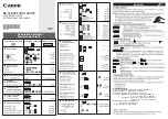
FRONT PANEL CONTROLS AND INDICATORS
F1 - LCD Display - This displays the PS151 or selected
transcoder parameter and its setting.
F2 -UNIT SELECT (Left) and (Right) Buttons -
These select either the PS151 power supply or one of
ten SCT4860 transcoders. Information from the selected
unit will be displayed on the LCD display for parameter
adjustment. When either button is pressed once, the
LED of the selected transcoder will blink for about 3
seconds, but the unit selected will not change. The
second press within 3 seconds will increment ( ) or
decrement ( ) to the next higher or lower numbered
unit. The PS151 power supply menu falls between
transcoder numbers 10 and 1.
F3 - (Left) and (Right) Buttons - Use the left or right
buttons to navigate from screen to screen to view a
parameter setting. This will not alter any settings. If in the
adjust mode, stop at the parameter you wish to adjust and
use the (up) and (down) buttons to adjust.
F4 - (Up) and (Down) Buttons - Use the up and
down arrows to adjust a parameter value when in the
adjust mode. When not in the adjust mode, pressing the
(up) button will display the software version readout,
and pressing the (down) button will display the QAM
modulation output baud rate readout.
F5 - ENTER - Use the ENTER button to enter the adjust
mode or to save and load a new setting or settings. Hold
for 2 seconds until the display flashes to enter the adjust
mode. After adjustment using the up or down arrow
buttons, press again to save and load the new settings.
You may save one parameter at a time after it is adjusted
or wait until all adjustments are made and press to save
and load all at once.
F6 - FAN - One of five front panel cooling fans. To ensure
proper cooling, do not block these openings.
F7 - L BAND INPUTS - These are the L band inputs from
the LNB. The level must be between -70 and -25 dBm.
The L band frequency range will be in the 950 to 2150
MHz range.
F8 - LED - The LED on each SCT4860 will blink on and
off for approximately 3 seconds when that unit is selected.
When in the adjust mode, it will blink continuously. When
in the normal mode, it will be lit continuously whenever
power is applied.
REAR PANEL CONNECTIONS
R1 - RS232 OUT - This RS232 serial connector can
connect to the RS232 IN connector on another rack
containing a PS150, PS151, or PS100 power supply
(included transcoders could be SCT860, SCT1860,
SCT2860, SCT4860 or SCT4860 transcoders), thus
allowing computer control of multiple racks of these units
with the same PC connection.
R2 - RS232 IN - Connecting this RS232 serial connector
to the serial port of a personal computer equipped with
Drake RS232 remote control software, allows remote
monitoring and programming of each transcoder. Alterna-
tively, can be connected to the Drake SCTeci. No connec-
tion is required for front panel control.
R3 - Fan Power- Connect the two conductor cable from
the front panel fans to this connector.
R4 - Power Out - These connectors are for connecting
the power cables from each individual SCT4860 to the
PS151 power supply. The other end of each cable can be
plugged into any one of the ten transcoders. However,
to minimize confusion, it is strongly suggested that the
left most unit (as viewed from the front panel) be con-
nected to power supply socket number 1, the second
from the left to number 2, etc. Do not attempt to use any
power supply other than this Drake supplied model.
R5 - Power In - This connector supplies power and
program control to the SCT4860. Connect a cable from
this connector to the appropriate connector on the PS151
power supply (see R4 above).
R6 - RF Output - This is the QAM output channel RF
output. The frequency range is between 54 and 864 MHz
depending upon the channel selected. The output level
is +25 to +40 dBmV, nominal, adjustable in 1 dB steps.
NOTE: Although the above discussions refer to the
SCT4860 transcoder modules, other Drake transcoders
may be mixed with SCT4860s in the same RMT150 rack
mounting tray. These include the SCT1860, SCT2860,
and SCT3860. The PS151 power supply/control module
will recognize each type of transcoder.
Also, SCT860 transcoders, although controlled by a
different power supply model, the PS100, can have the
RS232 control 'daisy chained' with the PS150 and PS151
controlled transcoders.
F1
F2
F3
F4
F5
F6
F7
F8
ID 1.1
12.45 dB
ENTER
SELECT
UNIT
DRAKE TRANSCODER SYSTEM
RF OUTPUT
POWER
R1
R2
R3
R4
R5
R6
+12
+5
TX
+3
GND
RX
100 - 240 VAC
47 - 63 HZ, 125 W
FAN POWER
10
9
7
8
5
6
4
3
1
2
RS232 OUT
RS232 IN