8 Setup and Programming / Software Flow Chart
GENERAL
Programming and viewing of the various setup and operating
parameters are accomplished using the front panel back lit,
two line, sixteen character wide LCD along with the LEFT,
RIGHT, UP, DOWN and ENTER buttons. Generally, the name
of the parameter is on the top line of the display and the
setting value is on the bottom line. For some parameters,
both the parameter name and value are on the bottom line.
To observe a certain parameter setting without intending to
change its value, just use the LEFT and RIGHT arrow
buttons to navigate through the menus shown in the software
flow chart below. Generally, the current setting for each
parameter is shown on the bottom line of the display. Note
that depending upon certain settings, some screens are not
needed and will be skipped.
To make a change in the displayed parameter and its setting
and if this is the initial setup, you will want to enter the ‘adjust’
mode. To do this, press the ENTER button that is located in
the center of the four arrow buttons and hold in for several
seconds until a flashing
“^”
appears in the upper right hand
corner of the display. After you are in the adjust mode, use
the LEFT and RIGHT arrow buttons to navigate among
screens and use the UP and DOWN arrows to change the
parameter setting.
When certain numerical values are to be adjusted, one or
more asterisks (
*
) will appear above the digits to be ad-
justed. Use the UP and DOWN keys to change the value
of the digit, and the LEFT or RIGHT keys to move to another
digit. Note that the astrisk(s) will not appear when scrolling
through adjustable parameters using the LEFT arrow key
unless it has already been activated using the RIGHT arrow
key.
When ENTER is pressed, the new settings will be loaded
and stored and the unit will exit the ‘adjust’ mode. You may
wish to not press ENTER until you have gone through all
screens and settings and then press ENTER to save and
load all changes in one step, OR you can store just one or
several parameters at a time and reenter adjust mode to set
the next. Either method is acceptable.
The OBM100 has displays that show the number of frames
per second that are input from the ASI inputs and are being
sent to the RF output. Each frame that comes from the ASI
inputs contains seven packets of 188 bytes each (1316
bytes). If a connection to the headend (as defined by the
destination address) has not been established through an
ARP reply, then the characters that display the number of
frames per second for the ASI input is replaced with a "NC"
display.
The frames being sent to the RF output contain between one
and seven packets of 188 bytes, depending upon what is
being sent to the OBM100 from the headend controller. The
headend controller will need to send frames with seven
packets in each frame to allow the unit to function properly
when high data rates are being sent through the RF output.
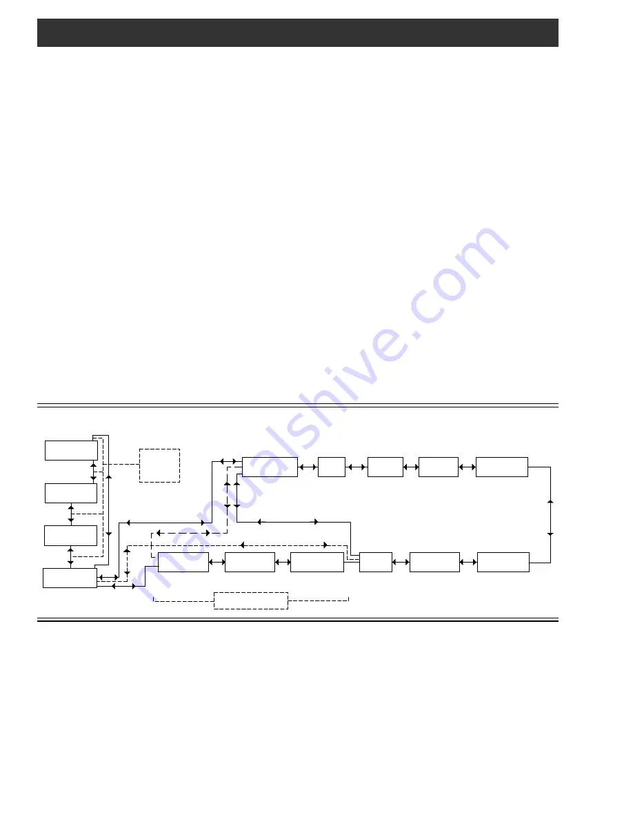
OBM100 QPSK DATA MODULATOR SOFTWARE FLOW CHART
SETTINGS
Frequency: Set the output frequency of the OBM100 as
required by the system map design. The frequency range is
from 70 to 130 MHz, adjustable in .05 MHz steps.
Output: Set the desired RF output signal level. The avail-
able range is from 30.0 to 52 dBmV in .5 dBmV steps. The
output accuracy is
± 1 dB.
OUTPUT MODE: For normal operation, select NORMAL.
For system level set up, choose CW to provide a CW carrier
at the center frequency of the output channel for use in
leveling a system when a QAM power meter is not available.
In the CW mode, the CW carrier can be measured on a
spectrum analyzer without a need to apply a bandwidth
correction or it can be measured with an analog meter tuned
to channel center. The CW power measured will equal the
channel QAM power when the modulator is returned to
normal output mode. Usually QAM signals are set 5 dB
below analog NTSC channels when balancing a system.
The PRBS menu entry is used for testing purposes only and
should normally not be selected by the user.
Symbol Rate: This setting allows selection of the output
symbol rate. Set as required by the set top boxes. The
choices are .772, 1.024, and 1.544 MHz.
Freq xxx.xx MHz
**
Output
Output
Mode
Symbol Rate
70 - 130 MHz
NORMAL
CW
PRBS
.772
1.024
1.544
Dest MAC
FFFFFFFFFFFF
000000000000 -
FFFFFFFFFFFF
Dest addr
255.255.255.255
*
*
Dest Port 65535
000.000.000.000 -
255.255.255.255
00000 -
65535
DHCP
enable
ON
OFF
255.255.255.255
*
IP addr
GATEWAY addr
255.255.255.255
*
SUBNET mask
255.255.255.255
*
255.255.255.255
000.000.000.000 -
255.255.255.255
000.000.000.000 -
255.255.255.255
000.000.000.000 -
DHCP ON (Adjust Mode)
DHCP OFF
(Adjust & Normal Modes)
DHCP ON (Normal Mode)
DHCP OFF
(Adjust Mode)
(Not User Settable)
30.0 - 52.0 dBmv
OBM100 1.4 c
DHCP...........
DHCP...........
or
xxx.xxx.xxx.xxx
Board Setup...
MAC xxxxxxxxxxxx
to RF Output
xxx Frames/S
xxx Frames/S
from ASI Input
DHCP OFF
(Normal Mode)
Up & Down
buttons in
normal mode
only.