10
Installation • Fuse Alarm Pins and Control Relays Pinouts
2.3.7 Fuse Alarm Pins and Control Relays Pinouts
Fuse Alarm
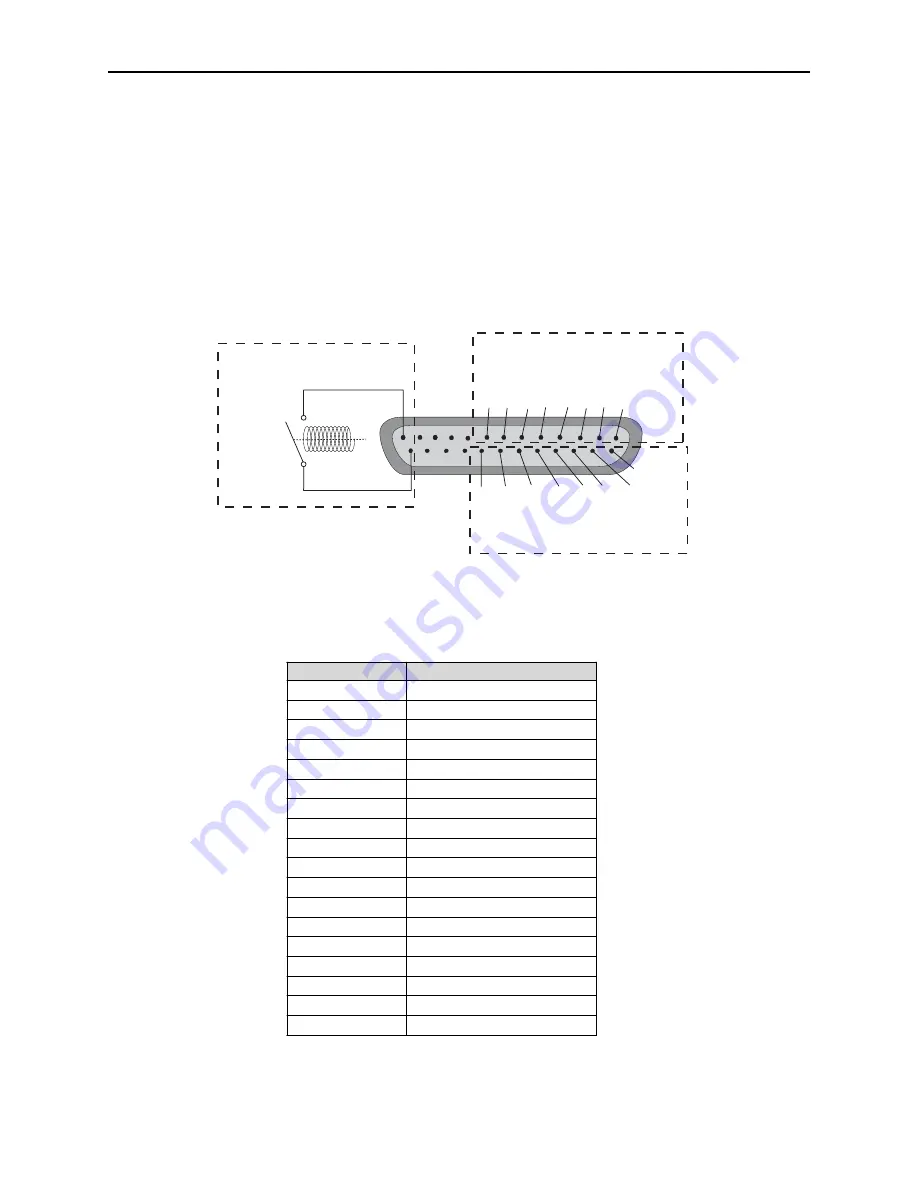
The fuse alarm relay is Normally Open. If the fuse blows, the fuse alarm (FA) LED will light and the fuse alarm
relay (FA RLY) will de-energize (close). The relay is found on pins 13 and 25 of the DB 25 connector on the back
panel. Connect these pins to other alarm monitoring equipment to give visibility of an equipment failure.(See fig-
ure 2.3.7 below). Refer to Table 2.3.7 for pinout information.
Control Relays
Controls can be used for starting or stopping equipment, unlocking doors, and other functions. Connect control
relays to the 25-pin connector on the back panel. Refer to Table 2.3.7 for control relay connection pinouts.
The default setting for the relays is Normally Open (N/O). To change the settings to Normally Closed (N/C), you
must reset the circuit board jumpers. For instructions on changing jumper settings, see Section 2.3.7.1.
1
13
14
25
8 7 6 5 4 3 2
21 20 19 18 17 16 15
Fuse Alarm Relays
Pins 1-8 Common
Pins 14-21 N/O & N/C
Fig. 2.3.7 -
The Fuse Alarm relay is found on pins 13 and 25, and the Control Relay pins are numbers 1-8
M ale D B 25 Pin
D escription
1
R elay 1 C om m on
2
R elay 2 C om m on
3
R elay 3 C om m on
4
R elay 4 C om m on
5
R elay 5 C om m on
6
R elay 6 C om m on
7
R elay 7 C om m on
8
R elay 8 C om m on
13
Fuse Alarm R elay Pin 1
14
R elay 1 (N /C or N /O )*
15
R elay 2 (N /C or N /O )*
16
R elay 3 (N /C or N /O )*
17
R elay 4 (N /C or N /O )*
18
R elay 5 (N /C or N /O )*
19
R elay 6 (N /C or N /O )*
20
R elay 7 (N /C or N /O )*
21
R elay 8 (N /C or N /O )*
25
Fuse Alarm R elay Pin 2
Tbl. 2.3.7 -
Alarm and control relays pinout information
* This pin is user selectable by an internal jumper - the default is always Normally Open.
Summary of Contents for D-PC-293-10A
Page 22: ...20 Notes ...


