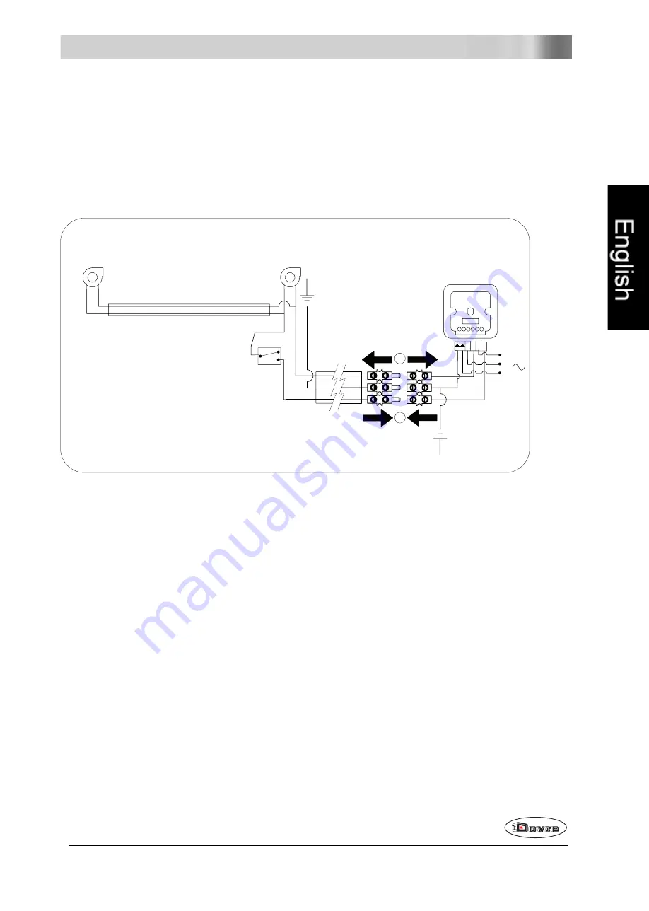
Appendix 2: Connection diagrams
The codes in the diagrams below have the following meaning:
T1
thermoswitch
V1
fan
V2
fan
VISTA 700i / 800i
V1
V2
230 V
M
N
M
L
1 2 3 4 5 6
1
2
T1
/
/
1
1. Disconnection of fan plate
2. Connection of fan plate
Subject to change because of technical improvements
23


