


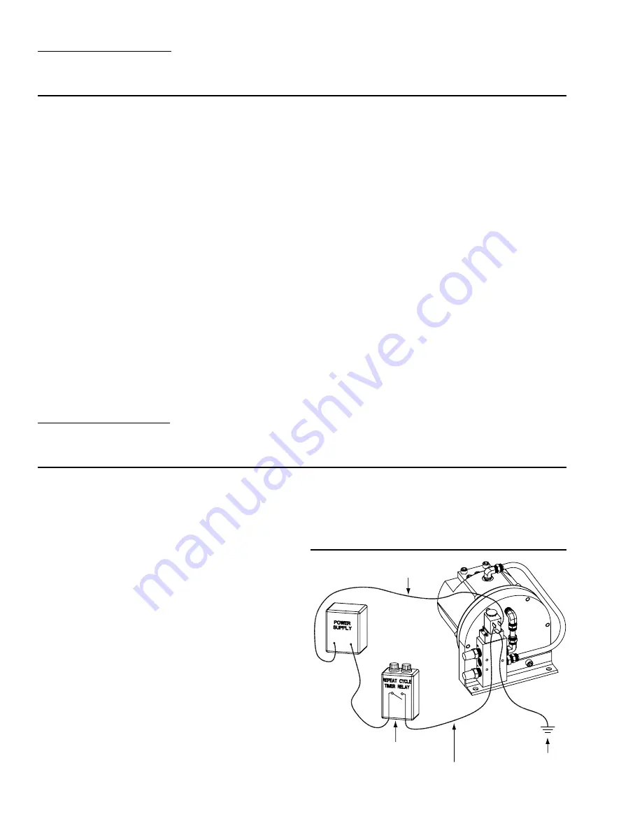
COMMON CONNECTION
FLICKER MODE RELAY
OR BATCH CONTROLLER
SWITCHED (CONTROL)
CONNECTION
GROUND
CONNECTION
SECTION 6D
SUGGESTED OPERATION AND
MAINTENANCE INSTRUCTIONS
OPERATION: The H25/1600S is pre-lubricated and does not
require in-line lubrication. Additional lubrication will not
damage the pump, however if the pump is heavily lubricated
by an external source, the pump operation may be affected.
It may need to be disassembled and re-lubricated as
described in the ASSEMBLY/DISASSEMBLY INSTRUCTIONS.
Pump discharge rate can be controlled by limiting the volume
and/or pressure of the air supply to the pump (preferred
method). A regulator is used to control air pressure while a
needle valve is used to control volume. Pump discharge rate
can also be controlled by throttling the pump discharge by
partially closing a valve in the discharge line of the pump.
This action increases friction loss which reduces flow rate.
(See Section 5.) This is useful when the need exists to control
the pump from a remote location. When the pump discharge
pressure equals or exceeds approximately 13 times the air
inlet pressure, the pump will stop; no bypass or pressure
relief valve is needed, and pump damage will not occur. The
pump has reached a “deadhead” situation and can be
restarted by reducing the fluid discharge pressure or increas-
ing the air inlet pressure. The Wilden R.025/1600S pump
runs solely on compressed air and generates little heat,
therefore your process fluid temperature will not be affected.
MAINTENANCE AND INSPECTIONS: Since each applica-
tion is unique, maintenance schedules may be different for
every pump. Frequency of use, line pressure, viscosity and
abrasiveness of process fluid all affect the parts life of a
Wilden pump. Periodic inspections have been found to
offer the best means for preventing unscheduled pump
downtime. Personnel familiar with the pump’s construction
and service should be informed of any abnormalities that
are detected during operation.
RECORDS: When service is required, a record should be
made of all necessary repairs and replacements. Over a
period of time, such records can become a valuable tool for
predicting and preventing future maintenance problems
and unscheduled downtime. In addition, accurate records
make it possible to identify pumps that are poorly suited to
their applications.
SECTION 6E
INSTALLATION—
ELECTRICAL CONNECTIONS
When the solenoid is unpowered, the back side of the power
piston is pressurized with air and the power/liquid piston
assembly is in its full discharge stroke position. When electric
power is applied, the solenoid valve shifts and the pressure
on the back side of the power piston is exhausted while the
front side of the power piston is pressurized with air. By alter-
nately applying and removing power, the solenoid operated
pump reciprocates.
The speed of the pump is controlled electrically. Since each
stroke is controlled by an electrical signal, the pump is ideal
for batching and other electrically controlled dispensing
applications.
Although the speed of the pump is controlled electrically,
the air pressure is important. Air pressure displaces the fluid,
and if the pressure is insufficient to complete the physical
stroke before an electronic impulse signals the pump to
shift, the shift will not be completed, and the displacement
per stroke will be reduced. This does not harm the unit in
any way, but it may cause inaccuracy when attempting to
batch specific quantities with high precision if this effect is
not taken into account.
There are three coil voltage options available. One coil allows
for 24V DC operation. The second coil option allows for
operation with either 12V DC or 24V AC at 50 or 60 Hz and
the third coil option allows for 110V AC operation.
ELECTRICAL CONNECTIONS
Summary of Contents for Wilden Advanced H25
Page 19: ...TT5178...


