background image

This manual provides information for:

OPERATOR MANUAL

IMPORTANT INFORMATION, KEEP FOR OPERATOR

PART NUMBER 128805 REV G (07/14)

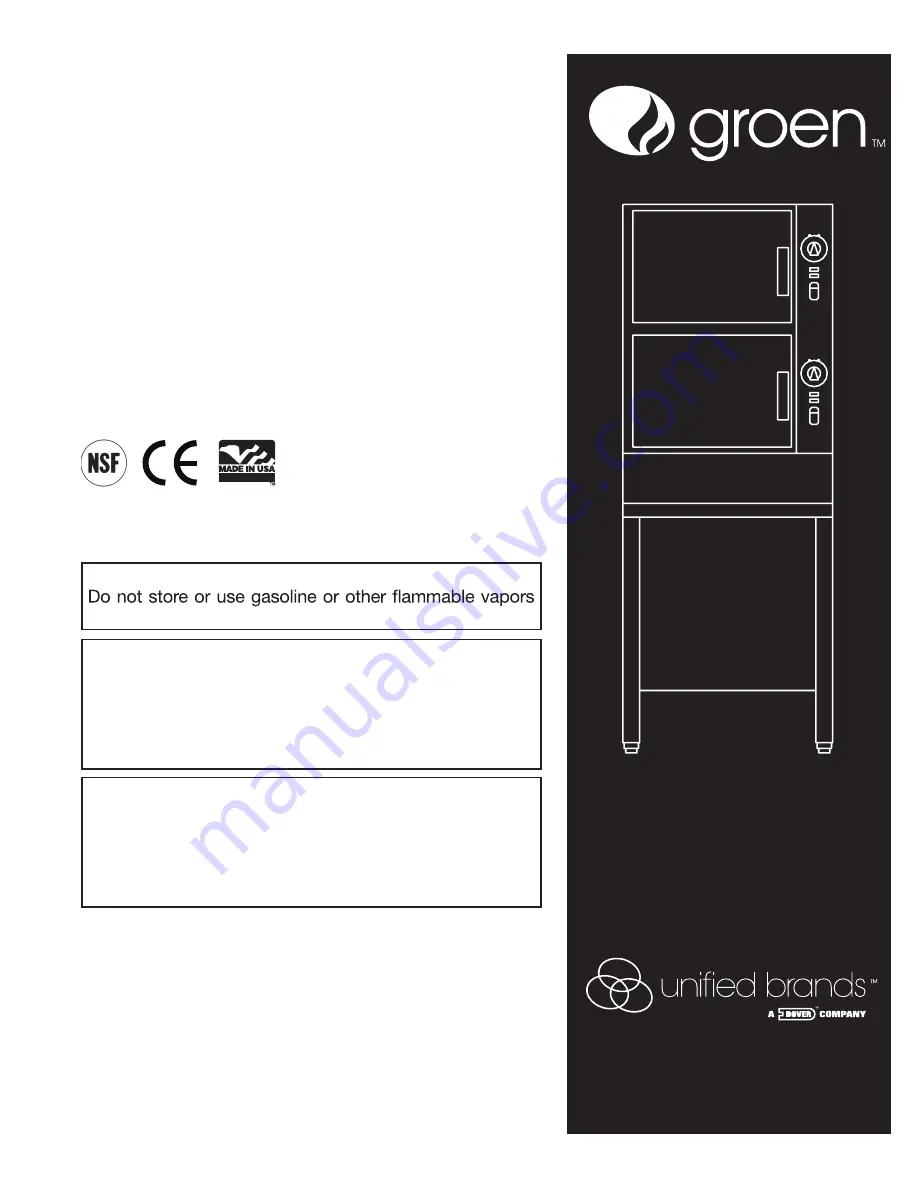
MODEL HY-6G(CE) 

HYPERSTEAM™ 

ATMOSPHERIC 

CONVECTION STEAMER

INTERNATIONAL

· Self Contained

· Gas

· Capacity: 6 Steamer Pans (12” x 20” x 2-1/2”)

  .

E

C

N

E

R

E

F

E

R


E

R

U

T

U

F


R

O

F


D

E

N

I

A

T

E

R


E

B


T

S

U

M


L

A

U

N

A

M


S

I

H

T

READ,  UNDERSTAND  AND  FOLLOW  THE  INSTRUCTIONS  AND 

WARNINGS CONTAINED IN THIS MANUAL.

WARNING / FOR YOUR SAFETY

and liquids in the vicinity of this or any other appliance.

POST IN A PROMINENT LOCATION

Instructions to be followed in the event user smells 

gas.  This information shall be obtained by consulting 

your local gas supplier.  As a minimum, turn off the gas 

and call your gas company and your authorized service 

agent.  Evacuate all personnel from the area.

WARNING

Improper  installation,  adjustment,  alteration,  service 

or  maintenance  can  cause  property  damage,  injury  or 

death.  Read the installation, operating and maintenance 

instructions thoroughly before installing or servicing this 

equipment.

NOTIFY CARRIER OF DAMAGE AT ONCE

It is the responsibility of the consignee to inspect the container upon receipt of 

same and to determine the possibility of any damage, including concealed dam-

age. Unified Brands suggests that if you are suspicious of damage to make a 

notation on the delivery receipt. It will be the responsibility of the consignee to file 

a claim with the carrier. We recommend that you do so at once.

Manufacture Service/Questions 888-994-7636.

Information contained in this document is known to be current and accurate at the time 

of  printing/creation.  Unified  Brands  recommends  referencing  our  product  line  websites, 

unifiedbrands.net, for the most updated product information and specifications.

1055 Mendell Davis Drive 

Jackson, MS 39272

888-994-7636,  fax 888-864-7636

unifiedbrands.net

Summary of Contents for Unified Brands Groen HyperSteam HY-6G

Page 1: ...tallation adjustment alteration service or maintenance can cause property damage injury or death Read the installation operating and maintenance instructions thoroughly before installing or servicing this equipment NOTIFY CARRIER OF DAMAGE AT ONCE It is the responsibility of the consignee to inspect the container upon receipt of same and to determine the possibility of any damage including conceal...

Page 2: ... CONVERSANT WITH THE APPROPRIATE PROVISIONS OF THE FIRE PRECAUTIONS ACT AND THE REQUIREMENTS OF THE GAS SAFETY REGULATIONS IN PARTICULAR THEY SHOULD BE AWARE OF THE NEED FOR REGULAR SERVICING BY A COMPETENT PERSON TO ENSURE THE CONTINUED SAFE AND EFFICIENT PERFORMANCE OF THE APPLIANCE WARNING TO PREVENT SHOCKS ALL APPLIANCES GAS OR ELECTRIC MUST BE EARTHED UPON COMPLETION OF THE INSTALLATION THE O...

Page 3: ...ng page 17 Electrical Schematic page 25 Service Procedures page 26 39 Service Log page 40 UNDERWRITERS LABORATORIES INC 333 Pfingsten Road Northbrook Illinois 60062 KLENZADE SALES CENTER ECOLAB Inc 370 Wabasha St Paul Minnesota 55102 800 328 3663 or 612 293 2233 NATIONAL FIRE PROTECTION ASSOCIATION 60 Batterymarch Park Quincy Massachusetts 02269 NFPA 70 The National Electrical Code NSF INTERNATION...

Page 4: ... mm A 1 5 mm stainless steel case encloses the cavities the steam generators and the control compartment that houses electrical components Door hinges are reversible the doors may be set to open from the left or right Operating Controls are on the front panel HY 6G CE steamers are equipped with fully electronic controls and a button activated pre programmed CLEAN cycle The drain system includes a ...

Page 5: ...ss than 60 ppm TDS 30 to 60 ppm Chlorine and Chloramine less than 0 1 ppm Total Chloride less than 30 ppm Silica less than 12 ppm Undissolved Solids less than 5 microns 1 Do not rely on unproven water treatments which are sold for scale prevention or scale removal They don t always work The best way to prevent scale is to supply the purest possible water 30 60 ppm TDS 2 If your water contains scal...

Page 6: ...onal injury Strap edges may be very sharp particularly where cut Write down the model number serial number and installation date Space for these entries is provided in the Service Log at the back of this manual Keep the manual near the equipment for reference and update as needed When installing use material handling equipment to lift the unit straight up from the skid Check packing materials for ...

Page 7: ...ection to fixed wiring A suitably rated isolating switch with contact separation of at least 3 mm on both poles must be fitted to the installation Wiring must be executed in accordance with the regulations listed on page 2 of this manual Cable entry is at the bottom rear right side of the appliance To gain access the panel must be removed Open the lower front panel by removing its screws Lift the ...

Page 8: ...cked by connecting a manometer to the pressure tap on the burner manifold The adjusted gas pressures is shown in the table below If necessary the gas pressure may be readjusted as described in the Service Manual NOTE With reference to gas rate pressure adjustments and conversions this appliance is CE approved for use with C20 natural gas and G31 propane gas in Ireland and the United Kingdom Use of...

Page 9: ...eated Water Second Connection As discussed previously the flow of water used for steam suppression in the drain is much greater than the amount of water used to generate steam The second connection on steamers see illustration under Water Quality Treatment section permits the installer to supply treated water to the steam generator and untreated water to the drain With split water feature the init...

Page 10: ...e trial for ignition During the initial start up the pilot may require several trials for ignition until all the air is bled from the gas piping Subsequent start ups should require only about 5 seconds to achieve pilot ignition Reinstall panel s NOTE See Automatic Operation of Pilot at the end of this section 7 Once the pilot burner flame has been established the green light on the electrical pane...

Page 11: ...pilot burner ever fails to re ignite automatically within 90 seconds wait 5 minutes before you attempt to reactivate it In the unlikely event that ignition problems persist contact your authorized Groen Service Agency NOTE For operation at high altitudes 2000 feet and above please consult the Groen Food Service Engineering Department 12 Gas Type Conversion See Paragraph 3 on page 9 for important i...

Page 12: ...w boil or holding temperature 2 When a cook time is set the unit steams until the timer reaches OFF The steaming stops a red light comes on and a beeper sounds 3 With the timer turned to the ON position the unit steams continuously The green light stays lit The steamer will not time down Gas Lockout Indicator and Reset Control Should the pilot fail to ignite during start up a yellow indicator on t...

Page 13: ... will come on and a beeper will sound Steam production stops To steam continuously turn the timer to the manual ON position A green light will come on The unit will continue steaming until you stop it by turning the timer to OFF When steaming continuously YOU MUST CONTROL STEAMING TIME 5 Open the door Remove the pans from the steamer using hot pads or oven mitts to protect your hands from the hot ...

Page 14: ...e 34 Puritan Puribrute or Con Lie e Cloth or sponge f Plastic wool or a brush with soft bristles g Spray bottle h Measuring cup i Nylon pad j Towels k Plastic disposable gloves l Funnel B Procedure 1 Outside a Prepare a warm solution of the mild detergent as instructed by the supplier Wet a cloth with this solution and wring it out Use the moist cloth to clean the outside of the unit Do not allow ...

Page 15: ...When the steamer beeper sounds turn off the steamer and open the door After the fan has stopped remove the fan baffle partition and rinse it well in a sink Wipe out the cavity completely If necessary use a damp nylon pad j Reinstall the fan baffle k If the steamer will no longer be used leave it off Otherwise wait 10 minutes and turn it back on When the READY light comes on the steamer is ready fo...

Page 16: ...seen leaking from around the door take the following steps 1 Check the door gasket Replace if it is cracked or split 2 Inspect the cooking chamber drain to be sure it is not blocked 3 Adjust the latch pin to allow for changes that might occur as the gasket ages a Loosen the lock nut at the base of the latch pin Turn the latch pin turn clockwise and re tighten the lock nut b After adjustment run th...

Page 17: ...horized Service Rep Only g Is spark ignition cable connected to module X Steam generator does not fill with water User a Is the ON OFF touch pad depressed b Is the water supply connected c Is the water turned on d Check for low water pressure less than 210 kPa or 30 PSI e Is the screen at the water connection clogged f Has the steam generator been delimed No steam User a Is the ON OFF touch pad de...

Page 18: ...788 9 Door Locking Pin 078914 9a Door Pin Lock Nut 003823 10 Timer Knob 123100 11 Mylar Overlay Plate 123128 12 Vent Pipe 141346 13 Upper Right Side Panel 139941 14 Lower Back Panel 139945 15 Sink Drain Fitting 099943 16 Upper Left Panel 139942 17 Top Panel 143116 18 Flue Cover 096765 19 Flue 096854 20 Back Panel 21 Timer 100983 22 Equipotential Terminal Assy 122021 23 Water Supply Adapter Assy 12...

Page 19: ...Steam Port 088874 6 Steam Port Gasket 099250 7 Steam Hose Top 099953 8 Steam Hose Bottom 088880 9 1 3 8 Hose Clamp 127525 10 Fan Motor 096740 11 Motor Capacitor 3 MFD 096813 12 Cover Control Panel 128800 13 Steamer Control PC Board 137221 14 Transformer 119815 15 Timer Board 119817 16 Top Cavity Drain Hose 088847 x Bottom Cavity Drain Hose 088846 x not shown ...

Page 20: ... Reset Switch Pushbutton 122003 11 Circuit Breaker 10 Amp 119860 12 Lug Ground 119829 13 Main Gas Valve 122158 14 Regulator 100513 15 Steam Generator Assy LH 094128 16 Steam Generator Assy RH 123655 Key Description Part 1 Gas Valve 24V 122120 2 1 2 Tubing 123707 3 3 8 Tubing 096712 4 Heat Shield 123711 5 1 2 Tubing 123475 6 3 8 Tubing 123706 7 1 4 Tubing Pilot 122140 8 Manifold Fitting Assembly 12...

Page 21: ...ter Assy BSPT 122144 8 Steam Gen Drain Valve 071234 9 Outer Gen Drain Hose 099911 10 Inner Gen Drain Hose 099912 11 Gen Drain Hose Clamps 095656 12 Drain Box 096791 13 Drain Box Flap 099213 14 Drain Box Cover 096792 15 Top Cavity Drain Hose 088847 16 Bottom Cavity Drain Hose 088846 x Cavity Drain Hose Clamp 21 4 073259 18 Vent Pipe 096855 19 Water Inlet Valve 2 Way treated water 071235 x Water Inl...

Page 22: ...0 x Timer Fastener Nut 101145 3 Motor Shaft Seal 096868 4 Motor Insulator 094135 5 Fan 096790 6 Timer 50 Hz 100983 7 Timer Knob 123100 8 Door Switch 096857 9 Steam Port Kit 118102 10 Ready Thermostat 088865 11 Steam Port Gasket 099250 x not shown includes thermostat and steam port gasket ...

Page 23: ... Gen Insulation 096770 4 Safety Valve 106392 5 Drain Box Spray Nozzle 081670 6 Water Level Probe 070178 7 Top Cavity Drain Hose 088847 8 Bottom Cavity Drain Hose 088846 9 Top Steam Hose 099953 10 Sink Drain Hose 099915 x Water Inlet Hose 096772 12 Inner Steam Generator Drain Hose 099912 13 Outer Steam Generator Drain Hose 099911 14 Condensate Hose 096771 15 Bottom Steam Hose 088880 x not shown ...

Page 24: ...05 123704 4 Igniter Module 154059 5 Solenoid Gas Valve 122120 6 Pilot Gas Switch 087951 7 Water Inlet Valve 3 outlet prior to 10 2010 090827 8 Steam Generator Drain Valve 071234 9 Pilot Burner Natural Gas 123641 10 Water Inlet Valve 2 outlet treated water 071235 11 Water Inlet Valve 1 outlet for untreated condensate cooling 100934 x Flame Sensor 003328 x not shown 10 11 ...

Page 25: ...OM HY 6G CE 25 Electrical Schematic ...

Page 26: ...anels are identical and interchangeable C Left Side Removal P N 123184 Under normal conditions the left side cover should never have to be removed as there are no operational and or replacement parts to be accessed The single exception is if the door has been reversed so that the handle is on the LEFT and the Door Interlock Switch is found to be defective and must be replaced The door switches for...

Page 27: ...g water use of regular untreated water is recommended has a inlet with one solenoid activated valve Color of wires are Solenoid Wires Top Steam Generator Fill Red and Black Bottom Steam Generator Fill Violet and Black Condensate Spray Black and White 4 Slide the hose clamps down the hose until needed for reassembly Loosen and remove the hoses using a gentle rocking motion 5 From the back of the st...

Page 28: ...pipe compound on the nozzle threads insert nozzle in socket wrench and start the nozzle in the hole Tighten nozzle 6 Replace cover on drain box and lower vent pipe into the drain box I Steam Generator P N 094128 123655 1 Shut off power water and gas supply to the steamer 2 Turn main gas valve to the OFF position 3 Disconnect the water inlet hose steam hose and drain hose by loosening the hose clam...

Page 29: ...terminals These will snap on and off the terminal post Unsnap them by gently pulling on the terminal 4 Using an open ended wrench turn the probe counter clockwise to remove To Install 5 Apply high temperature pipe compound to the probe and screw it in by hand Using an open ended wrench tighten the probe into the fitting 6 Replace the wire s to the probes by snapping the fork terminals around the t...

Page 30: ...ch connects the assembly to the main gas valve 4 From the left side or back of the steamer use a wrench to loosen and disconnect the aluminum tubing to the inner and outer manifolds 5 The entire assembly of both regulators and the gas solenoid valves for the upper and lower steam generators may be removed as an integrated unit 6 Remove the gas solenoid valve s as required To Reinstall 7 Clean pipe...

Page 31: ...r color coded wires from the switch assembly 2 The switch snaps into the metal plate where it is retained by plastic tabs on the top and bottom To remove the switch from the plate press in on both tabs at the same time and slide the switch out of the bracket hole To replace the switch 3 Insert the new switch into the bracket hole until its tabs clear the hole and snap into position 4 Reattach the ...

Page 32: ...nd green wire from the igniter module 3 Connect a DC micrometer between the igniter ground terminal and the disconnected green wire 4 Ignite the pilot The micrometer should read 3 microamps minimum If current reading is correct replace the igniter module see 10 13 If current reading is below 3 microamps continually check the Flame Rectification Circuit large orange wire spark electrode pilot burne...

Page 33: ...ite from the timer mechanism and unplug the two black timer motor leads 4 With an open ended wrench remove the hex nut holding the timer in place The timer may then be removed from inside the compartment NOTE Right below the timer shaft the timer has a small plastic disk molded onto the case There is a corresponding hole punched into the front panel This hole may be seen from the inside of the com...

Page 34: ...le Refer to the Motor Assembly Chart 6 Insert the steamer motor seal in the cutout of the insulator board 7 To prepare motor for mounting slide the oil slinger washer onto the shaft about 12 mm down the shaft IMPORTANT This washer has two surfaces A rubber surface and a phenolic surface Make sure the phenolic surface is facing the motor 8 Install the plate seal holder onto the motor shaft Carefull...

Page 35: ... and sliding it away from the steam port Turn and pull to loosen hose and remove from steam port 3 With a wrench remove the screws holding the thermostat to the steam port 4 Cut and fold up aluminum foil insulation blanket to expose the two nuts which hold the steam port to the cavity wall threaded studs 5 With a wrench remove the two nuts 6 Remove the steam port To Install 7 Put a small bead of s...

Page 36: ...flat clean table or similar support with gasket facing up Be careful not to scratch door surface 3 Inspect door gasket for signs of cuts or other defects which may impair its function Replace if necessary To Install 4 To install the door apply NEVER SEEZ lubricant to hinge pin Align door with hinge and insert hinge pin To Align 5 Place a piece of masking tape over the door pin bullet hole in the d...

Page 37: ...at the opposite end of the door channel with the magnet facing outward from the door 9 Remove screws which secure the handle Remove door handle from cam 10 Apply NEVER SEEZ high temperature rated for 250ºC anti seize and lubricating compound to the cam and Locktite 242 to screw threads 11 Turn handle and cam 180 degrees from their original positions and install them on the door with screws Be sure...

Page 38: ...242 to the door to hinge bolts then install door and mounting bolts Do NOT tighten mounting bolts at this time 13 Align door to steamer per Paragraph X BB Door Handle Magnet and Block Assembly Door Handle P N 070123 Magnet Block P N 069762 Screws P N 005764 Door Cam P N 074252 U Channel Assy P N 094144 Outer Door Panel P N 094140 Inner Door Panel P N 094141 Door Insulation Bd P N 094192 1 Turn ste...

Page 39: ... the U channel top end first then lower channel into position Check that spring opens when door handle is pushed up 10 Apply Locktite 242 to U channel mounting screws then install the screws 11 Replace the two screws in the U channel applying Locktite 242 to secure them in place DD Door Locking Pin P N 078914 Lock Nut P N 003823 1 Turn steamer off and allow it to cool 2 Note and record the distanc...

Page 40: ...40 OM HY 6G CE Service Log Model No Purchased From Serial No Location Date Purchased Date Installed Purchase Order No For Service Call Date Maintenance Performed Performed By ...

Page 41: ...OM HY 6G CE 41 ...

Page 42: ...42 OM HY 6G CE ...

Page 43: ...OM HY 6G CE 43 ...

Page 44: ... REV G 07 14 1055 Mendell Davis Drive Jackson MS 39272 888 994 7636 601 372 3903 Fax 888 864 7636 unifiedbrands net 2014 Unified Brands All Rights Reserved Unified Brands is a wholly owned subsidiary of Dover Corporation ...

Reviews: