PAGE 17
SERVICE INSTRUCTIONS
CONTINUED
338 REV.031001
2) Slide keyed washer item 149, and lockwasher item 161, onto output shaft against tapered roller bearing item
151. Screw locknut item 159, onto output shaft against lockwasher. Tighten locknut to a point where 5 to 15
pounds of pull is required to rotate output shaft item 150, freely. Bend tabs of lockwasher into openings on
locknut to lock output shaft into position.
3) Press new, well-greased oil seal item 157, into end cover item 156, and place new, well-greased O-ring item
167, onto flange.
4) Fasten end cover to final housing item 100, using six capscrews item 163, and lockwashers item 165.
5) Reassemble final planet hub assembly. Press needle bearing item 323, into planet gear item 320. Position
thrust washers item 321, on either side of planet gear and press planet pin item 310, into planet hub. Retain
with circlip item 411.
6) Insert final planet hub assembly into final housing. Ensure that planet hub spline is fully engaged.
7) Install final sungear item 340. Verify circlip item 341, is installed on sungear.
REASSEMBLY OF PRIMARY DRIVE:
If primary plant hub assembly was disassembled, reassemble by reversing disassembly procedure.
1) Press sungear stopper item 444, into primary planet hub item 400.
2) Press needle bearing item 423, into planet gear item 420.
3) Position thrust washers item 421, on either side of planet gear and press planet pin item 410, into planet hub.
4) Retain with circlip item 411.
REASSEMBLY OF BRAKE HOUSING ASSEMBLY:
Reassemble brake housing assembly by reversing disassembly procedure.
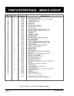
1) Install new, well-greased O-rings item 751 and 753, into glands of brake piston item 750.
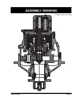
2) Slide brake piston into brake housing with holes for brake springs facing out of brake housing (see BRAKE
GROUP drawing).
3) Install 16 brake springs item 752, in brake piston. Piston has 18 holes and two holes which have no brake
springs installed should be located opposite to each other.
4) Install new, well-greased oil seal item 775, into spring stopper item 770, and press ball bearing item 777, into
place.
5) Press planet hub stopper item 304, onto spring stopper item 770, and install new, well-greased O-ring item 779.
6) Install spring stopper item 770, onto brake housing item 700, using six capscrews item 771, and lockwashers
item 773. Tighten capscrews, one turn at a time, to evenly compress brake springs item 752.
7) Install new, well-greased O-ring item 107, into outer flange O-ring groove in brake housing and fasten brake
housing to final housing item 100, with 16 capscrews item 111, and lockwashers item 113.
8) Install primary planet hub assembly through ball bearing item 777, and oil seal item 775, engaging teeth with
final sungear item 340.
9) Install primary sungear item 440.
10) Install two thrust washers item 615, (with thrust bearing item 617, between) on top of planet hub item 400.
11) Install internal gear item 430, on top of thrust washer, engaging teeth of three planet gears item 420.
12) If needle bearing item 603, was replaced, press into connecting shaft item 600. Slide brake hub item 720,
onto connecting shaft and fasten with retaining ring item 602. Install connecting shaft assembly into internal
gear item 430.


