background image

PAGE 10

After the PULLMASTER planetary winch has been installed in accordance with the INSTALLATION INSTRUCTIONS
the wire rope can be fastened to the cable drum.

IMPORTANT:

The ropes, chains, slings, etc. are not part of the winch and are not covered by this manual.
Refer  to manufacturer’s handling, inspection and maintenance recommendations to avoid
potential accidents. For selection of ropes, etc. please check following product standards: DIN
15020, prEN818-1/9, prEN 1492-1/2, prEN 1677-1/3 and other relevant product standards.

1) The cable drum of the PULLMASTER planetary winch has two cable anchor slots, one for clockwise and one

for counterclockwise hoisting. Standard rotation for hoisting is clockwise when looking at the hydraulic motor
of the unit. It is critical to select the cable anchor slot which will permit winding of the wire rope on the
drum in the correct direction of rotation. If the wire rope is wound on the cable drum in the wrong direction
of rotation, the winch will have no braking capacity. Each winch is shipped from the factory with a label on
the drum, indicating the correct cable anchor slot.

2) On wire rope installation, care must be taken that the wire rope is wrapped completely around the cable anchor

and properly pulled into the cable anchor slot in the cable drum. The cable drum require 5 wraps of wire rope
for safety.

3) Rapid reverse winches have more line speed and less allowable line pull when lowering. Refer to

SPECIFICATIONS for hoisting and lowering values.

4) The winch operation is controlled by a single control valve lever which has a forward, a reverse and a neutral

position. Speed control in either direction is obtained by modulation of the control valve lever. Maximum line
speed in either direction is obtained when the control valve lever is moved as far as it can go. The disk brake
of the winch will come on automatically when the winch control lever is returned to neutral.

5) Always warm up equipment prior to operating winch, particularly in low ambient temperature. Circulate

hydraulic oil through the winch control valve for several minutes to warm the hydraulic system. To prime the
winch with warm oil, operate the winch at slow speed, forward and reverse, several times.

6) To ensure proper winch installation and function, raise and lower a full test load to a safe height before using

winch for regular operation at the start of each shift.

If, after a new installation, the winch does not function properly, refer to the TROUBLE SHOOTING section
of this manual.

248 REV.251117

WIRE ROPE INSTALLATION
Clockwise hoisting winch shown.
(Use cable anchor slot on opposite
side of drum for counterclockwise
hoisting winch.)

Feed the wire rope through the cable
anchor slot. Loop rope back into slot
as shown. Insert cable anchor into
slot, small end first and long side
nearest the drum flange. Pull rope
 tight to wedge rope in slot.

FAILURE TO FOLLOW INSTALLATION INSTRUCTIONS WILL

RESULT IN PROPERTY DAMAGE, SEVERE INJURY OR DEATH.

DANGER

OPERATING INSTRUCTIONS

SI1013-8

CABLE ANCHOR SLOT

CABLE ANCHOR

Summary of Contents for Pull MASTER H8

Page 1: ...Y HYDRAULIC WINCH READTHISMANUALBEFOREINSTALLING OPERATINGORSERVICING THISPRODUCT THISMANUALCONTAINSIMPORTANTINFORMATION MAKE THIS MANUAL AVAILABLE TO ALL PERSONS RESPONSIBLE FORTHEOPERATION INSTALLATION SERVICINGANDMAINTENANCE OF THIS PRODUCT Click Here To Visit ...

Page 2: ...ver failures of the unit which result in any manner from the operation of the machine or unit at vibration frequencies at or near the natural frequency vibration of the machine in such a way that damage may result Buyer expressly agrees that Seller is not responsible for failure damage or accelerated wear caused by machine or ambient vibration Further Buyer acknowledges and agrees that Buyer is al...

Page 3: ...Other use as foreseen in the functional description of the hydraulic winch is not allowed without written permission from PULLMASTER FAILURE TO COMPLY WITH THE FOLLOWING SAFETY RECOMMENDATIONS AND LOCAL RULES AND REGULATIONS WILL RESULT IN PROPERTY DAMAGE SEVERE INJURY OR DEATH Definition Caution indicates a potentially hazardous situation which if not avoided may result in minor or moderate injur...

Page 4: ... is eliminated and the output torque and rpm of the hydraulic motor are transmitted directly to the final planet reduction stage With the primary reduction stage eliminated the reduction is reduced to a ratio of 7 8 1 and the cable drum will rotate 4 3 times faster than in forward or hoisting speed If the load on the cable drum tends to effect the lowering speed the resulting pressure drop in the ...

Page 5: ...xternal brake release clockwise drum rotation external circulation flow 9 Automatic brake external brake release counterclockwise drum rotation external circulation flow 10 Automatic brake counterclockwise drum rotation external circulation flow HYDRAULIC MOTOR 30 WM31 hydraulic motor 2 inch gear section Other gear sections for this motor are optional DRUM SIZE 1 7 inch drum diameter X 11 1 2 inch...

Page 6: ...n be supplied with optional drums to accommodate large wire rope storage capacity DRUM GROOVING CabledrumsforthePULLMASTERModelH8planetarywinchcanbegrooved Wherethisoptionisarequirement it is necessary to state the size of wire rope which is to be used with the winch OPTIONAL GEAR SECTION FOR THE HYDRAULIC MOTOR The performance of the standard PULLMASTER Model H8 planetary winch may be changed by ...

Page 7: ... OPERATING VOLUME 37 US gpm 140 l min MINIMUM OPERATING VOLUME 11 US gpm 42 l min DRUM TORQUE AT MAXIMUM PRESSURE 31 875 lb in 3 601 Nm DRUM RPM AT MAXIMUM VOLUME HOISTING 59 rpm LOWERING 256 rpm HOISTING LINE PULL AT MAXIMUM PRESSURE Bare drum 8 500 lb 37 8 kN Full drum 5 795 lb 25 8 kN MAXIMUM ALLOWABLE LINE PULL WHEN LOWERING Bare drum 1 962 lb 8 7 kN Full drum 1 342 lb 6 0 kN HOISTING LINE SPE...

Page 8: ... 0 0 6 7 13 3 20 0 26 7 33 4 40 0 138 110 83 55 28 0 LINE PULL lb OIL PRESSURE psi OIL PRESSURE bar 0 0 0 LINE SPEED fpm 30 60 91 121 151 OIL VOLUME US gpm OIL VOLUME l min HOISTING LINE PULL VS OIL PRESSURE MAXIMUM ALLOWABLE LINE PULL WHEN LOWERING BARE DRUM 1962 lb 8 7 kN FULL DRUM 1342 lb 6 0 kN LINE SPEED VS OIL VOLUME Performance graphs are based on standard hydraulic motor gear ratio and cab...

Page 9: ...R MODELS SUPPLIED WITH EXTERNAL BRAKE RELEASE OPTION FILTER HYDRAULIC PUMP RESERVOIR CONTROL VALVE MOTOR SPOOL 4 WAY SPRING RETURN TO CENTER PRESSURE RELIEF VALVE CIRCULATION SUPPLY LINE M8 3 US GPM 11 LPM H8 4 US GPM 15 LPM EXTERNAL CIRCULATION MODELS ONLY CIRCULATION RETURN LINE DIRECT TO RESERVOIR ...

Page 10: ...ELIEF The hydraulic circuit for the PULLMASTER planetary winch requires a pressure relief set at the operating pressure see SPECIFICATIONS Usually a pressure relief is part of the hydraulic control valve Where this is not the case a separate pressure relief valve must be installedandsetattherecommendedmaximumpressure HYDRAULIC RESERVOIR It is recommended that the hydraulic reservoir has sufficient...

Page 11: ...kness in the space between the mounting pad and the mounting surface c Only after this procedure should the fourth mounting bolt be installed Tighten all four bolts as per torque chart at back of manual 4 Fill the winch with lubricating oil See APPENDIX A for oil volume required 5 Use recommended circuit components and hydraulic hoses 6 The circulation return line of the winch should be plumbed in...

Page 12: ...wering Refer to SPECIFICATIONS for hoisting and lowering values 4 The winch operation is controlled by a single control valve lever which has aforward a reverse and a neutral position Speed control in either direction is obtained by modulation of the control valve lever Maximum line speed in either direction is obtained when the control valve lever is moved as far as it can go The disk brake of th...

Page 13: ...line speed or rpm of the winch Therefore if the winch does not produce the specified maximum rated line speed or drum rpm a loss of hydraulic flow somewhere in the hydraulic circuit can be analysed If this condition exists install a flow meter into the hydraulic circuit to check the volume of oil supplied to the pressure port of the hydraulic winch motor when the winch control is completely opened...

Page 14: ...used by a complete lack of or insufficient circulation flow To check the circulation observe the flow of oil from the circulation returnlineofthewinch approx 3 5 US gpm 13l min when the winch is reversed c Controlvalveforthewinchoperationhaspoormetering characteristics d Damaged brake plates or divider plates e The over running clutch which connects the motor shaft with the brake assembly is damag...

Page 15: ...or calibrations are necessary Proceed with the disassembly as follows DISASSEMBLY OF HYDRAULIC MOTOR ASSEMBLY If the analysed service or repair work requires access to the interior of the brake housing the hydraulic motor should not be disassembled In this case the hydraulic motor should be removed together with the motor adaptor as a complete assembly If a problem has been analysed to be in the h...

Page 16: ...tems 727 and 731 3 Remove circlip item 727 from the motor drive shaft to take off sprag clutch item 723 sprag clutch spacer item 726 support washer item 717 and sprag clutch aligner item 724 4 Thoroughly inspect the surface of the motor drive shaft where the sprag clutch engages If any indentation or surface damage is detected replace motor drive shaft sprag clutch and connecting shaft as a set 5 ...

Page 17: ... inspect planet hub stopper item 126 and sungear stopper item 122 for excessive wear Replace if planet hub stopper is less than 14 inch or if sungear stopper is less than 37 inch thick 3 Remove final planet hub assembly from final housing item 100 Winches with optional B reduction ratio only 3A Inspect planet hub stopper item 128 and replace if necessary 4 Inspect three final planet gears item 320...

Page 18: ...item 320 Position thrust washers item 321 on either side of planet gear and press planet pin item 310 into the final planet hub item 300 Retain with circlip item 311 5 Insert final planet hub assembly into final housing item 100 Ensure that planet hub spline is fully engaged with cable drum item 500 6 Verifycirclip item343 isinstalledonsplinedendoffinalsungear item340 Insertfinalsungearthroughcent...

Page 19: ...5 onto brake hub item 720 7 Slide the brake hub item 720 onto the spline of the connecting shaft item 600 ensuring that thrust washer item 615 does not fall off and secure with circlip item 513 248 REV 971001 SERVICE INSTRUCTIONS CONTINUED 8 Install brake spacer item 712 into brake housing Starting and finishing with a divider plate alternately install nine divider plates item 714 and eight fricti...

Page 20: ...ng a soft headed hammer 4 Installthegearset item881 inthegearhousing thelongergearwiththeinternalsplinegoesintothetopposition 5 Press the other thrust plate complete with six new pocket seals onto the bearings installed in the port end cover so the pocket seals are facing the port end cover 6 Install the port end cover item 870 together with two bearings item 875 and a new ring seal item 877 onto ...

Page 21: ...mounting 2 Disassemble the winch as per instructions 3 Discard and replace all O rings and oil seals 4 Clean all parts and inspect for wear and damage as per instructions Replace worn or damaged parts as required 5 Reassemble the winch as per instructions 6 FollowINSTALLATIONandOPERATINGINSTRUCTIONSwhenreturningwinchtoitsmounting When ordering parts for the PULLMASTER Model H8 planetary winch alwa...

Page 22: ...IP ROTOR CLIP SH 87 313 3 25004 CIRCLIP ROTOR CLIP C 87 320 3 FINAL PLANET GEAR 321 6 25068 THRUST WASHER TORRINGTON TRA 1423 323 3 25168 NEEDLE BEARING TORRINGTON B1418 340 1 FINAL SUNGEAR 343 1 25273 CIRCLIP ANDERTON A1000 0137 500 1 CABLE DRUM 502 1 20085 CABLE ANCHOR 503 1 25085 PIPE PLUG 3 8 NPT 513 1 25055 CIRCLIP ROTOR CLIP SH 262 550 1 BASE 551 12 25013 CAPSCREW HEX HEAD 1 2 13NC X 1 25 GR...

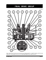
Page 23: ...in a specific assembly Parts that are referenced on the drawing but are not on the PARTS REFERENCE list should be ignored 248 REV 960101 FINAL DRIVE GROUP B REDUCTION ONLY 128 320 310 503 124 321 130 123 323 311 313 109 103 122 126 120 121 300 100 553 551 550 502 513 105 500 343 340 ...

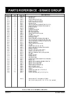
Page 24: ...1 25196 O RING 030 1 5 8 ID 1 16 CS 627 1 25232 NEEDLE BEARING TORRINGTON B2012 700 1 21375 BRAKE HOUSING 703 1 25331 PLASTIC CAPLUG 3 4 NPT THR D 707 1 25192 O RING 173 8 1 2 ID 3 32 CS 710 1 21179 BACK UP WASHER FOR OIL SEAL 25195 711 1 25195 OIL SEAL 712 1 21377 BRAKE SPACER 714 9 21252 DIVIDER PLATE 715 8 25194 FRICTION PLATE 717 1 25729 SUPPORT WASHER ANDERTON R 28 40 2 0 720 1 20261 BRAKE HU...

Page 25: ...248 REV 990325 BRAKE GROUP PRIOR TO SERIAL NO 37799 Item 723 Was Part No 25071 Borg Warner sprag clutch X13143 Qty 2 Item 726 Was not required PRIOR TO SERIAL NO 56185 Item 727 Was Part No 25411 Item 730 Was Part No 21457 730 707 724 717 726 720 752 750 753 751 703 700 515 509 508 605 600 430 413 412 420 400 411 410 423 421 444 731 727 513 714 715 712 615 617 440 723 711 623 622 625 627 620 621 71...

Page 26: ...17 GEAR SET 030 COMM 312 2820 007 885 2 25320 THRUST PLATE COMM 391 2185 059 887 1 25321 SEAL STRIP COMM 391 2882 051 899 2 25031 PIPE PLUG 1 4 18 NPT 929 1 950 1 SUB ASSY MOTOR 030 COMM WM31 2 0 951 4 25324 CAPSCREW HEX HEAD 5 8 X 5 25 COMM 391 1401 103 953 4 25325 WASHER COMM 391 3784 028 955 2 25556 PLASTIC CAPLUG 1 312 12 THR D 23131 MOTOR SEAL KIT CONSISTS OF ITEMS 869 877 AND 887 NOTE ITEM 9...

Page 27: ...actually present in a specific assembly Parts that are referenced on the drawing but are not on the PARTS REFERENCE list should be ignored 248 REV 950715 MOTOR GROUP 877 803 955 899 870 875 865 861 887 821 823 881 804 802 801 800 805 807 809 885 869 929 951 953 950 ...

Page 28: ...IRCULATION MODELS ONLY MOTOR PORTS SAE O RING BOSS SEE MOTOR CHART FOR SIZES 4 MOUNTING HOLES 21 32 17 USE 5 8 MOUNTING BOLTS GRADE 5 OR BETTER DRAIN PORT 1 2 14 NPT CIRCULATION RETURN PORT 3 4 14 NPT F E A PRESSURIZE FOR CLOCKWISE ROTATION PRESSURIZE FOR COUNTER CLOCKWISE ROTATION B K M FOR SAFETY A MINIMUM OF 5 WRAPS OF WIRE ROPE MUST BE MAINTAINED AT ALL TIMES FILLER PORT 3 8 18NPT STANDARD CAB...

Page 29: ... 321 321 381 342 90 499 221 174 6 203 20 327 DRUM CODE 4 in 7 0 13 5 12 0 4 8 13 6 12 6 19 0 17 500 23 6 8 7 6 88 8 000 12 9 mm 178 343 305 122 346 321 483 444 50 599 221 174 6 203 20 327 HYDRAULIC MOTORS COMMERCIAL WM31 SERIES MOTOR CODE GEAR WIDTH MOTOR PORT SIZE SAE O RING 30 31 32 33 34 2 00 50 8 1 75 44 5 1 50 38 1 1 25 31 8 1 00 25 4 1 5 16 12 1 5 16 12 1 1 16 12 1 1 16 12 7 8 14 L 5 4 137 5...

Page 30: ...PAGE 28 G1050 B G1052 B G1086 248 REV 000830 ASSEMBLY DRAWING ...

Page 31: ...2 116 170 502 736 0 4 178 292 203 46 51 69 37 8 25 8 8 7 6 0 35 52 153 224 1 5 2 7 0 13 5 8 0 231 297 375 8500 4904 1962 1159 116 201 502 870 0 4 178 343 203 70 91 114 37 8 21 8 8 7 5 2 35 61 153 265 1 5 4 7 0 13 5 12 0 347 445 562 8500 4904 1962 1159 116 201 502 870 0 6 178 343 305 106 136 171 37 8 21 8 8 7 5 2 35 61 153 265 2 3 POUNDS KILONEWTONS POUNDS KILONEWTONS LUBRICATING OIL VOLUME REQUIRE...

Page 32: ...DE STANDARD REDUCTION RATIO PART NUMBERS 1 N A 20143 20113 20142 20174 20074 2 N A 20143 20113 20142 20298 20074 4 N A 20143 20113 20352 20324 20325 DRUM CODE 1 20314 20353 20355 22174 20174 20074 2 20314 20353 20355 22174 20298 20074 4 20314 20353 20355 22094 20324 20325 B REDUCTION RATIO PART NUMBERS 1 N A 20109 20102 20104 20174 20074 2 N A 20109 20102 20104 20298 20074 4 N A 20109 20102 20351 ...

Page 33: ...5374 25085 N A 22028 N A 21483 N A 25040 N A N A 25085 N A 22029 N A N A 25040 25040 N A N A N A 26276 22303 20849 N A 25040 N A 25622 25374 N A 26276 22083 20849 N A 25040 N A 25622 25374 N A 26276 22084 N A N A 25040 25040 N A N A N A 26276 22304 802 804 804 807 807 809 929 929 950 1 8 27 NPT PIPE ADAPTOR 1 8 27 NPT PIPE PLUG PLASTIC CAPLUG 1 8 NPT 3 8 18 NPT PIPE PLUG PLASTIC CAPLUG 3 8 NPT MOT...

Page 34: ...18 24 3 8 32 43 7 16 50 68 1 2 75 102 9 16 110 149 5 8 150 203 3 4 265 359 7 8 420 569 1 640 868 1 1 8 800 1085 1 1 4 1000 1356 248 REV 950715 TORQUE lb ft NOTE Unless otherwise specified torque bolts per above chart BOLT TORQUE CHART Click Here To Visit ...

Reviews: