


ALF-13250-E-01
All-Flo
8
SECTION
6
INSTALLATION, TROUBLE-
SHOOTING AND MAINTENANCE
INSTALLATION
PIPING
Whenever possible ensure the pump is installed using
the shortest possible pipe lengths with the minimum
amount of pipe fittings. Ensure all piping is supported
independent of the pump.
Suction and discharge piping should not be smaller
than the connection size of the pump. When pumping
liquids of high viscosity, larger piping may be used, in
order to reduce frictional pipe loss.
Employ flexible hoses in order to eliminate the vibration
caused by the pump. Mounting feet can also be used to
reduce vibration effects.
All hoses should be reinforced, non-collapsible and be
capable of high vacuum service. Ensure that all piping
and hoses are chemically compatible with the process
and cleaning fluid.
For processes where pulsation effects should be
reduced, employ a pulsation dampener on the discharge
side of the pump.
For self-priming applications, ensure all connections
are airtight and the application is within the pumps
dry-lift capability. Refer to product specifications for
further details.
For flooded suction applications, install a gate valve
on the suction piping in order to facilitate service.
For unattended flooded suction operation, it is
recommended to pipe the exhaust air above the liquid
source. In the event of a diaphragm failure this will
reduce or eliminate the possibility of liquid discharging
through the exhaust onto the ground.
LOCATION
Ensure that the pump is installed in an accessible
location, in order to facilitate future service and
maintenance.
AIR
Ensure that the air supply is sufficient for the
volume of air required by the pump. Refer to product
specifications for further details. For reliable
operation, install a 5 micron air filter, air-valve and
pressure regulator. Do not exceed the pumps
maximum operating pressure of 120 psig.
REMOTE OPERATION
Utilize a three way solenoid valve for remote
operation. This ensures that air between the solenoid
and the pump is allowed to “bleed off,” ensuring
reliable operation. Liquid transfer volume is estimated
by multiplying displacement per stroke times the
number of strokes per minute
NOISE
Correct installation of the muffler reduces sound
levels. Refer to product specifications for
further details.
SUBMERGED OPERATION
For submersible operation, pipe the air exhaust to
atmosphere
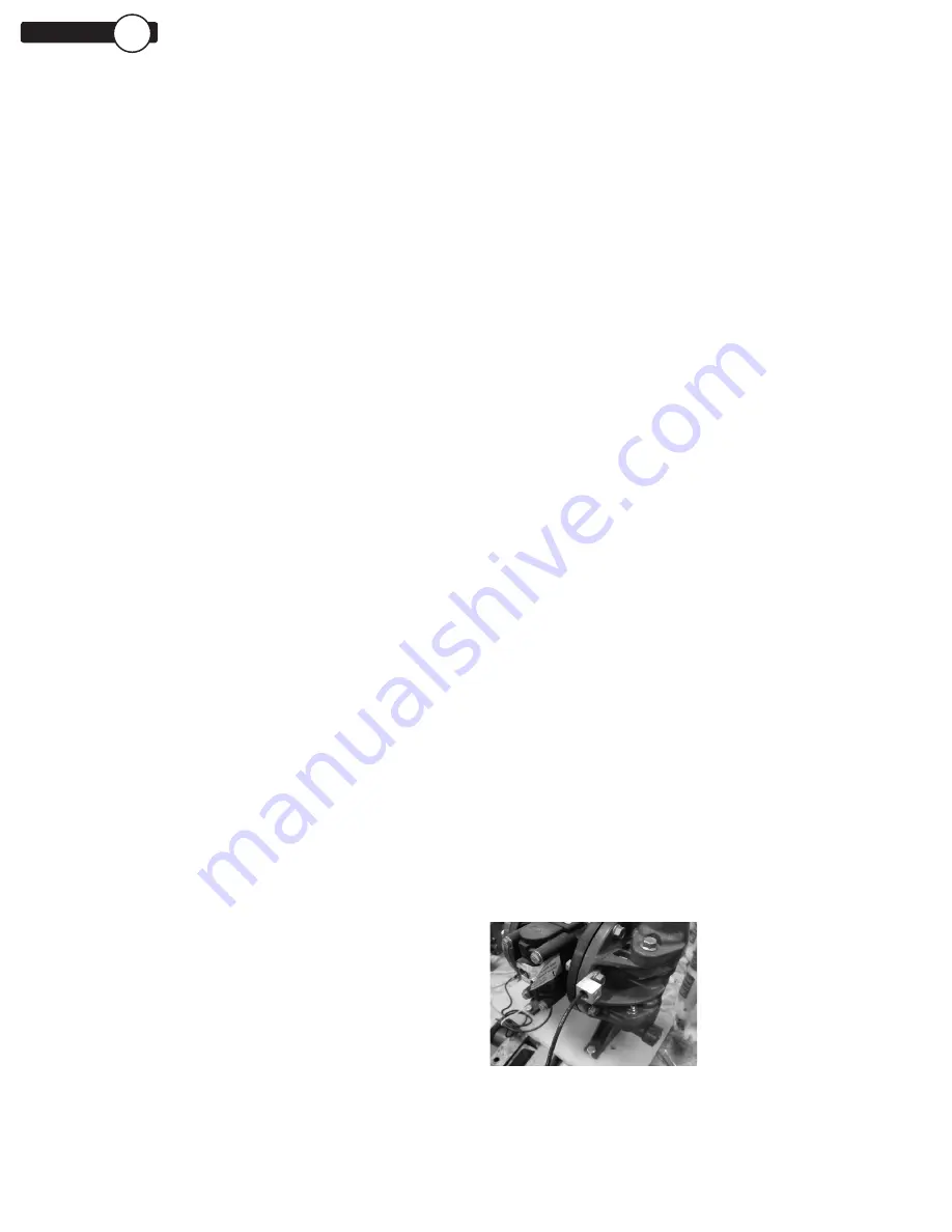
GROUNDING THE PUMP
Loosen grounding screw and install a grounding wire.
Tighten grounding screw. Wire size should be a 12
gauge wire or larger. Connect the other end of the wire
to a true earth ground. Equipment must be grounded
to achieve ATEX rating and it is recommended to
configure the pump with a grounding lug option.
Summary of Contents for PSG C100
Page 1: ...IOM INSTALLATION OPERATION MAINTENANCE C100 PLASTIC 1 INCH AIR OPERATED DOUBLE DIAPHRAGM PUMP ...
Page 6: ...ALF 13250 E 01 All Flo 6 1 PUMP DIMENSIONS CLAMPED PLASTIC SECTION 4 ...
Page 18: ...ALF 13250 E 01 All Flo 18 EXPLODED VIEW PARTS LIST C100 SP CLAMPED PLASTIC SECTION 8 ...


