G1
CASE TOP FASCIA
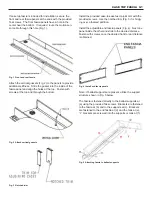
If case top fascia is included for installation, secure the
front and rear fascia panels at the ends with the provided
Tek screws. The front fascia panels have a hole in the
center near the bottom. If required, route the motion sen-
sor cable through this hole (Fig. 1).
Attach the vertical gussets (Fig. 2) to the panels to provide
additional stiffness. Slide the gusset into the inside of the
fascia panel and align the holes at the top. Fasten with
screws at the top and through the bottom.
Install the provided case-to-case fascia joint trim with the
provided screws. Use the notched trim (Fig. 3) for bridg-
ing over a foamed partition.
Install the adjustable end fascia panels (Fig. 4). Nest one
panel inside the other and slide to the desired distance.
Fasten with screws once the desired front to rear distance
is obtained.
Fig. 1 Front and rear fascia
Fig. 2 Attach vertical gussets
Fig. 3 Notched trim
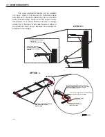
Note: If ballast supports are present, utilize the support
structure shown in Fig. 5 below.
The fascia is fastened directly to the ballast supports at
(a) using the provided Tek screws. Brackets are fastened
to the fascia at (b) and to the supports at (c). Brackets
are fastened to the end fascia at (d) and the tank at (e).
“L” brackets are screwed into the supports or tank at (f).
Fig. 4 Install end fascia panels
Fig. 5 Attaching fascia to ballast supports
Summary of Contents for Hillphoenix ONRZ
Page 23: ...ELECTRIC DEFROST 1 PHASE E2 ELECTRICAL WIRING ...
Page 24: ...E3 ELECTRIC DEFROST 3 PHASE ELECTRICAL WIRING ...
Page 25: ...E4 ELECTRIC DEFROST HOT GAS ELECTRICAL WIRING ...
Page 31: ...J2 SEISMIC BRACKETS 5 BRACKETS ...
Page 32: ...J3 SEISMIC BRACKETS 7 BRACKETS ...
Page 33: ...J4 SEISMIC BRACKETS 11 BRACKETS ...


