OM/SM-AH-CE
5
1.2 Siting
1.5 Electrical Supply
Install the appliance on a level floor in a well-lit
This unit is designed for connection to fixed
and draught-free position. Install the appliance in
wiring. A suitably rated isolating switch with
accordance with local and/or national regulations
contact separation of at least 3 mm on both poles
as listed in this manual.
must be fitted to the installation and the wiring
1.3 Installing Clearances
Minimum clearances of 150 mm from the sides of
the appliance and 150 mm from the rear of the
appliance are required if the appliance is installed
next to combustible surfaces.
Allow 1000 mm minimum clearance between the
top rim of kettle and any overlying surface.
1.4 Ventilation
The unit must be installed in an adequately
ventilated room with provision for an adequate air
supply. The area around the appliance must be
cleared of all combustible material. For multiple
installations requirements for individual units
should be added together. Installation must
comply with applicable regulations. A competent
installer must be employed.
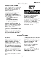
CAUTION
THE APPLIANCE FLUE DISCHARGES
VERTICALLY FROM THE TOP OF THE UNIT.
IT MUST NOT BE DIRECTLY CONNECTED TO
A FLUE, MECHANICAL EXTRACTION
SYSTEM, OR DUCTING LEADING OUTSIDE
THE BUILDING. THE APPLIANCE IS BEST
DISCHARGED UNDER AN OPEN CANOPY
CONNECTED TO A VENTILATING SYSTEM.
Recommendations for ventilation for catering
natural and propane gases without any
appliances are given in BS 5440:2 and are shown
conversion.
in the table below.
Equipment
Ventilation Rate
m³/Min
ft³/Min
Range
17
600
Pastry Oven
17
600
Fryer
26
900
Grill
17
600
Steak Grill
26
900
Boiling Pan
17
600
Steamer
17
600
Sterilizing Sink
14
500
Bains Marie
11
400
Tea/Coffee Machine
8.5-14
300-500
executed in accordance with the regulations listed
in this manual.
Cable entry is at the lower rear on right hand side
of the appliance. Access to the terminals is
gained by removing relevant panels as described
in Section 3.5 of this manual.
Provide 230 VAC, 50 Hz, 1 Phase, service. Rated
input: 0.17 Amps, or 40 Watts. The electrical
schematic is located in the service compartment
and in this manual.
WARNING
THIS APPLIANCE MUST BE EARTHED.
1.6 Gas Supply
The incoming service must be of sufficient size to
supply full rate without excessive pressure drop.
A gas meter is connected to the service pipe by
the Gas Supplier. Any existing meter should be
checked by the Gas Supplier to ensure that the
meter is of adequate capacity to pass the required
rate of gas for the kettle in addition to any other
gas equipment installed.
The appliance governor is incorporated in the gas
control valve which is situated in the control
cabinet.
The control valve governor is suitable for both
Installation pipe work should be fitted in
accordance with IEGE/UP/2. The pipe work
should not be smaller than the gas inlet
connection on the kettle, i.e. Rp ½ (½”B.S.P.)
An isolating cock must be located close to the
appliance to allow shut down during an
emergency or servicing. The installation must be
tested for gas soundness and purged as specified
in IGE/UP/1.
1.7 Water Supply
Not applicable to these appliances.
Summary of Contents for GROEN AH-20
Page 23: ...OM SM AH CE 23 ...
Page 24: ...OM SM AH CE 24 Parts Lists ...


