


TL 1128 (TOP HOLES)
Issued August 2016
Revision No: 006
Printed in U.S.A.
Copyright 2016, Bayne Premium Lift Systems
Actuator Assembly Instructions
21
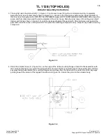
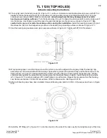
12.Place the rack cap (5) ( Figure C-13 ) bore side up on the table and coat the edge of each bore with STP Oil
Treatment. Install the rack cap seals (14) ( Figure C-9 ) in the rack cap.
Figure C-9
13.Reposition the actuator on the table mounting flanges down, and the lower tubes facing away from the assembler.
Rotate the pinion shaft to allow 1” of the rack to protrude from the top of the actuator body. Install the rack cap with
the oil port positioned to the left hand side of the actuator opposite the bottom oil port located in the tube cap as
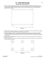
shown in Figure C-13. Attach the rack cap to the actuator body using the socket head bolts (22) ( Figure C-13 ) and
lock washers (26). Torque the bolts to 90 ft-lb. in the sequence shown in Figure C-10.
Figure C-10
14.Reposition the actuator so that the pinion shaft can be rotated with no obstacles. Rotate the pinion shaft to ensure
that the racks move freely. Also make sure that the key ways point perfectly straight “up” toward the rack cap and
“down” toward the tube cap at each end of the 180° stroke. If the assembly does not perform all of these functions
correctly, it must be disassembled, cleaned, and reassembled.
15.Re-center the actuator pinion in the actuator body by tapping on one end of the shaft with a rubber mallet. Install the
roller bearing (9) ( Figure C-13 ), over the pinion shaft and inner race, and into the actuator body. Repeat this
procedure for the other bearing.