21
20
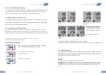
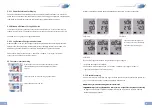
channel. The bottom status line shows battery capacity, logger mode and alarm status.
The green LED
flashes
every
30
seconds
during
recording.
The red LED is used to display limit alarms or status messages (battery change)
...
etc.). The logger also has an internal buzzer that supports the user interface. This product is
exclusively intended for the field of application described above. It should only be used as described
within these instructions. Unauthorized repairs, modifications or changes to the product are prohibited
and void any warranty!
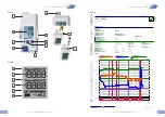
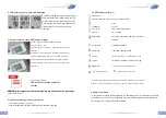
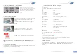
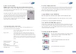
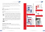
5. How to use device
5.1 Device description Fig. A (
see
5.1 Device description Fig. A (
see
page 2)
1. USB cover
2. USB connector
3. LCD display see Fig. B
4. LED: green / red
5. Sensor compartment
(position of the sensor)
6. Battery case
7. Mode button,
8. Start / Stop button
9.
lockable wall holder
10. External probes (TC only)
11. External probe (E only)
If the display has been deactivated (display off via Software LogConnect), the battery symbol and the symbol for
recording (►) or configuration (II) are still active in Line 4 (status line).
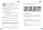
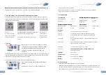
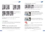
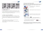
FIG. B (
see page 2)
FIG. B (
see page 2)
1. Units of measurement line 1
2. Measurement line 1
3. Units of measurement line 2
4. Measurement line 2
5. Line3 for indication and extreme
measurements
EXT * = external probe (only visible when
external probe is connected) * TC * AVG =
average value, Min = minimum value, Max =
maximum value
(no symbol) = current measurement value
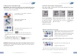
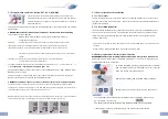
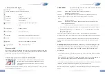
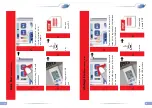
5.2 Device start-up
ATTENTION!
Please observe our battery recommendation strictly. Use only battery type LS 14250
ATTENTION!
Please observe our battery recommendation strictly. Use only battery type LS 14250
3.6 volt from manufacturer SAFT or DYNAMIS Lithium Batt. LI-110 1/2 AA / S, respectively, only
batteries authorized by the manufacturer. For operation take out the instrument from the packaging,
remove the display foil. The logger is already preset and ready to start. It can be used immediately
without any software! By pressing any button or moving the instrument before first operation the
instrument displays FS (factory setting) for 2 seconds, afterwards measurements are displayed for 2
minutes. Then the instrument display switches off. Repeated key hit or movement reactivates the
display.
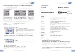
5.2.1 Factory settings
Note the following default settings of the data logger before first use. By using the LogConnect *
software, the setting parameter can easily be changed: Recording Interval:
5 min. LOG210 / LOG220, / LOG200 TC / LOG210 TC / LOG220 E 15
min. LOG200 / LOG200 E
Measuring interval:
During recording the measurement interval and recording interval are the
same! If the logger has not started (NOT RECORDING) the measuring
interval is every 6 seconds for 15 minutes, afterwards the measuring interval
is every 15 min. for 24 hours, afterwards the measuring interval is once per
hour. If you press any button or move the device it will start again to measure
every 6 seconds.
Start possible by:
Key press
Stop possible by:
USB connect
Alarm:
off
Alarm delay:
0 s
Show measurements on display:
on
Power-Save mode for display:
on
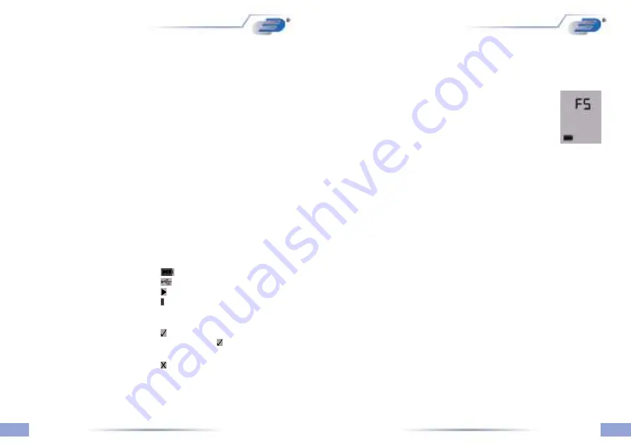
6. Line4 status line (from left to right): Battery
indication, USB connection indication,
Data logger is recording, Data logger has
been configured by LogConnect and is
waiting for action, Data logger has been
stopped and OK, (without
► Symbol) Data logger has
been stopped and X NOT OK
(eg Alarm level reached
(without ► Symbol)