background image

851-899 Rev. A

13

Dorner Mfg. Corp.

FlexMove FC (105 mm) Conveyor System

Installation

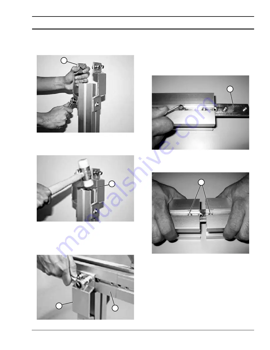
2. Insert the square nuts of the second support bracket 

(Figure 18, item 1)

 into the support beam T-slots. Slide 

the bracket down so that it does not protrude above the 
cross-section of the beam.

 Figure 18

 Figure 18           

3. Use a soft hammer or mallet to mount an end cap 

(Figure 19, item 1)

 on to the support beam.

 Figure 19

 Figure 19           

4. Mount the first support bracket 

(Figure 20, item 1)

 to 

the conveyor beam 

(Figure 20, item 1)

. Pull the second 

bracket up and insert the T-bolts into the conveyor beam 
T-slot. Tighten the nuts.

 Figure 20

 Figure 20           

Conveyor Beam Installation

The next step is to connect conveyor beams – straight 

sections and bends – to each other. Connect all conveyor 

beams according to the instructions below.
1. Connect two conveyor beam ends by inserting 

connecting strips 

(Figure 21, item 1)

 into the beam 

inner T-slots. Use two connecting strips per beam joint.

 Figure 21

 Figure 21           

2. Make sure that the set screws 

(Figure 22, item 1

do not 

prevent the connection strips from sliding into place.

 Figure 22

 Figure 22           

1

1

1

2

1

1

Summary of Contents for FlexMove FC

Page 1: ...99 Rev A For other service manuals visit our website at www dornerconveyors com manuals literature Record Conveyor Serial Number Here FlexMove FC 105 mm Conveyor System Installation Maintenance Parts Manual ...

Page 2: ...hain End 19 Chain Installation at Drive Unit 20 Chain Assembly at Chain Disconnecting Module FCCC 21 Weighted Take Up 22 Top Running Drive 23 Install Guiding 24 Length Adjustment of the Conveyor Chain 24 End Drive Units and Catenary Drive Units 24 Intermediate Drive Units and Horizontal Bend Drive Unit 24 Guide Rail System Installation 24 High Side Guiding 25 Heavy Duty Fully Adjustable Guiding 25...

Page 3: ...ight Modules 71 4 5 High Sides for Curve Modules 72 4 5 High Sides for Incline Decline Modules 73 13 14 Heavy Duty Fully Adjustable Guiding 74 17 18 Puck Pallet Guiding 75 Type A Fixed Guiding 16x54 76 Type B Fixed Guiding 16x42 76 Type C Fixed Guiding 28x42 77 Type D Fixed Guiding 40x42 77 Type E Fixed Guiding 49x42 78 Type F Fixed Guiding 53x42 78 Type G Fixed Guiding 90x42 79 Type H Adjustable ...

Page 4: ...r s Limited Warranty applies Dorner has convenient pre configured kits of Key Service Parts for all conveyor products These time saving kits are easy to order designed for fast installation and guarantee you will have what you need when you need it Key Parts and Kits are marked in the Service Parts section of this manual with the Performance Parts Kits logo Dorner reserves the right to make change...

Page 5: ...WER before removing guards or performing maintenance A WARNING Gearmotors may be HOT DO NOT TOUCH Gearmotors A WARNING Dorner cannot control the physical installation and application of conveyors Taking protective measures is the responsibility of the user When conveyors are used in conjunction with other equipment or as part of a multiple conveyor system CHECK FOR POTENTIAL PINCH POINTS and other...

Page 6: ...FC 105 mm Conveyor System Product Description Refer to Figure 1 for typical components Figure 1 Figure 1 1 Infeed Module 2 Curve Module 3 Incline Module 4 Decline Module 5 Intermediate Module 6 Drive Module 7 Gearmotor 8 Stands 3 1 2 4 6 5 8 7 ...

Page 7: ... mm Conveyor System Specifications Conveyor Supports Maximum Distances 1 914 mm 36 2 3000 mm 118 3 914 mm 36 For conveyors longer than 3000 mm 118 install support at joint Note Additional support required on 180 curve modules Figure 2 Figure 2 3 2 1 ...

Page 8: ...s must be provided if products fall off the conveyor for some reason The same applies to all incline decline and vertical conveyors Considerations When correctly applied the conveyor components are safe to use or maintain It is however necessary for those responsible to design installation operation and maintenance to be aware of certain areas when special caution is required End Drive Unit The ch...

Page 9: ...er Countersink Cap Screw Nut Lock Nut M6 Washer Countersink Cap Screw Nut Lock Nut Figure 3 Figure 3 Square Nut Square nuts Figure 4 can be slid into T slot of FlexMove conveyor and support beams They do not stay in place in vertical positions and have to be inserted from the end of beam Remember to put in a sufficient number before completing the assembly Figure 4 Figure 4 Spring Nuts Spring nuts...

Page 10: ... carbide tip saw circulating at high speed for a clean cut The saw should have the ability of cutting the largest profile in one single cutting action Working Site You should use a special area for cutting beams in order to keep the assembly area clean Quality of Cut If burrs are evident they must be removed prior to assembly Make sure the cut is straight for proper assembly Assembly The basic Fle...

Page 11: ...ot connecting strips to the inner side of the foot Leave loose Figure 10 Figure 10 2 Slide the connecting strips Figure 11 item 1 into the structural beam T slots Figure 11 Figure 11 3 Raise the beam from the bottom of the foot approximately 40 50 mm Figure 12 item 1 to allow for height adjustment later in the assembly Figure 12 Figure 12 4 Tighten the screws using a wrench Figure 13 item 1 Figure...

Page 12: ...e 14 Option 2 Vertical beam support brackets Figure 15 item 1 are used with vertical support beams and are made from aluminum Figure 15 Figure 15 Option 3 Dual side mounting brackets Figure 16 item 1 are used to support 180 wheel corners Figure 16 Figure 16 Mounting Conveyor Beam Support Bracket 1 Attach screws nuts and washers to the support bracket Figure 17 item 1 before mounting Screws and squ...

Page 13: ...tem 1 to the conveyor beam Figure 20 item 1 Pull the second bracket up and insert the T bolts into the conveyor beam T slot Tighten the nuts Figure 20 Figure 20 Conveyor Beam Installation The next step is to connect conveyor beams straight sections and bends to each other Connect all conveyor beams according to the instructions below 1 Connect two conveyor beam ends by inserting connecting strips ...

Page 14: ...lace Figure 24 Figure 24 2 Tighten the set screws using a hex key Figure 25 item 1 Figure 25 Figure 25 Drive Tail Support Brackets 1 Attach the drive tail support brackets Figure 26 item 1 to the slot Figure 26 item 2 in the drive tail with the T bolts and hex nuts The brackets should be located closest to the frame Figure 26 item 3 Figure 26 Figure 26 Idler End 1 Insert the idler unit Figure 27 i...

Page 15: ...flange of the slide rail at the end of rail and press into place Figure 29 Figure 29 2 Make sure the slide rail Figure 30 item 1 is properly mounted and snaps onto the beam The longer flange of the slide rail must always face inside of the beam See Figure 31 Figure 30 Figure 30 Figure 31 Figure 31 A CAUTION The opening between the links when they turn around the idler could be a risk Idler ends sh...

Page 16: ...o make the chain run smoother This does not apply to slide rail that begins by an idler unit or after a drive unit where joints are always parallel Figure 35 Figure 35 Try to let the slide rail run in as continuous lengths as possible by reducing number of breaks except in circumstances stated below It is recommended to use short slide rails 2 3m 78 3 4 118 where chemicals may have an effect on th...

Page 17: ...radius the slide rail for the inner bend should be cut so that it is only 10 mm wide in the bend This is to prevent an uneven slide rail surface Stretch the slide rail while mounting Drilling Slide Rail 1 Drill two holes near the beginning of each slide rail section Use the drill fixture Figure 39 item 1 to ensure clean cut holes and the correct location of the holes The holes must be at the leadi...

Page 18: ...ing a hex driver until the screw is flush with the bottom of the slide rail Figure 41 Figure 41 2 Cut off the head of nylon screws by using flush cutting pliers Figure 42 item 1 or soft hammer and knife Figure 43 item 1 Remember the cut must be made away from the joint in the direction of chain travel Figure 42 Figure 42 Figure 43 Figure 43 3 After the cut make sure the slide rail surface is smoot...

Page 19: ...e of slide rail for protruding metal See Figure 47 Figure 47 Figure 47 Joining Chain End Assemble the chain by inserting the steel pin that comes with each chain link into the opposite end of another link Do this by using the FlexMove pin insertion tool 1 Insert the plastic pivot Figure 48 item 1 with the slot facing outward Figure 48 Figure 48 2 Insert the steel pin Figure 49 item 1 halfway using...

Page 20: ...rrect direction as indicated by the arrow Figure 53 item 1 located at the side of all chain links Figure 52 Figure 52 Figure 53 Figure 53 2 Feed the chain along the conveyor Figure 54 item 1 by pulling it through the idler unit and back to the drive unit Figure 54 Figure 54 3 Join 5 meter lengths of chain when necessary See Figure 55 Figure 55 Figure 55 4 Tension the chain and remove links if nece...

Page 21: ...7 2 Remove the flange Figure 58 item 1 so that the chain becomes accessible Figure 58 Figure 58 3 Clamp the chain Figure 59 item 1 to the beam profile Use the FlexMove chain tool Figure 59 item 2 to remove a steel pin from the chain so that two links are separated Figure 59 Figure 59 4 Remove excess links and use the chain tool Figure 60 item 1 to put the chain back together again Figure 60 Figure...

Page 22: ...plate Figure 62 item 2 of weighted take up assembly Figure 62 Figure 62 4 Raise weighted take up assembly Figure 63 item 1 with notch Figure 63 item 2 in assembly mating with stud Figure 63 item 3 on conveyor frame Figure 63 Figure 63 5 Install and tighten two screws Figure 64 item 1 on each side to secure assembly to frame Figure 64 Figure 64 Figure 65 Figure 65 NOTE Remove as much chain slack as...

Page 23: ...ll belt around conveyor ends and bring the ends of the belt Figure 67 item 1 together Figure 67 Figure 67 5 Insert the belt rod Use a punch and hammer or belt removal tool 203480 Figure 67 item 2 to press pin just below flush with side of belt Stop when pin detent is felt 6 Install drive motor mounting plate Figure 68 item 1 using four hex head cap screws Figure 68 item 2 Figure 68 Figure 68 7 Ins...

Page 24: ... the transmission guard cover The conveyor is now ready for operation Intermediate Drive Units and Horizontal Bend Drive Unit 1 Conveyors which have no conveyor chain slack should be assembled with a special section of conveyor beam FCCC which allows for the chain to be easily inserted and adjusted for tension See Chain Assembly at Chain Disconnecting Module FCCC on page 21 2 Remove the lower part...

Page 25: ... 3 Fasten retaining clip Figure 74 item 1 to conveyor with nut Figure 74 item 2 on stud Figure 74 Figure 74 4 Tighten nuts Figure 74 item 2 5 Install guide Figure 75 item 1 and retaining clip Figure 75 item 2 to conveyor side rail with socket head screw Figure 75 item 3 Figure 75 Figure 75 Heavy Duty Fully Adjustable Guiding 1 Install guide bracket assembly Figure 76 item 1 into the conveyor T slo...

Page 26: ...ure 78 item 1 on end of shaft Figure 78 item 2 to remove clip Figure 79 item 1 Figure 78 Figure 78 Figure 79 Figure 79 4 Snap clip Figure 80 item 1 onto guide rail Figure 80 item 2 Figure 80 Figure 80 5 Reassemble clip Figure 81 item 1 and attach to shaft Figure 81 item 2 Tighten screw Figure 78 item 1 on end of shaft Figure 81 Figure 81 6 Adjust rail width with top screw Figure 82 item 1 Figure 8...

Page 27: ...84 2 Fasten clip Figure 84 item 1 to conveyor with nut Figure 84 item 3 on stud 3 Tighten nuts Figure 85 item 1 Figure 85 Figure 85 4 Attach slide rail Figure 86 item 1 to guiding Figure 86 item 2 Figure 86 Figure 86 NOTE Make sure that the studs Figure 84 item 4 rotate inside the channel and engage with the conveyor 1 1 3 2 4 NOTE Be certain that slot Figure 85 item 2 is close to vertical when fi...

Page 28: ... T bolt Figure 88 item 2 Figure 88 Figure 88 2 Attach the guide rail Figure 89 item 1 to the clamp Figure 89 item 2 Tighten the screw Figure 89 item 3 Remember do not over tighten the screw Figure 89 Figure 89 3 Use a wrench Figure 89 item 4 to tighten the guide rail to the frame Remember do not over tighten the screw Install remaining brackets Assembly with Different Guide Rail Support Option 1 F...

Page 29: ...avy duty guide rail bracket Figure 92 item 1 with T bolt Figure 92 item 2 Figure 92 Figure 92 2 Attach the bracket onto conveyor beam and tighten with a socket wrench Figure 93 item 1 Figure 93 Figure 93 Assembly with Different Guide Rail Support Option 1 Figure 94 Figure 94 Option 2 Figure 95 Figure 95 Option 3 Figure 96 Figure 96 1 2 1 ...

Page 30: ...bracket onto conveyor beam and tighten with a socket wrench Figure 98 item 1 Figure 98 Figure 98 FGRB 40x18 FGRB 40x20 and FGRB 40x15x20 Guide Rail Bracket Assembly Method 1 1 Open the upper and lower caps Figure 99 item 1 on FGRB 40 guide rail bracket Figure 99 item 2 and install T bolt Figure 99 Figure 99 2 Attach the bracket onto conveyor beam and tighten with a socket wrench Figure 100 item 1 ...

Page 31: ...n the upper and lower caps Figure 103 item 1 and prepare the FGRB 40 guide rail bracket Figure 103 item 2 with T bolt Figure 103 Figure 103 2 Attach the bracket onto conveyor beam and tighten with a socket wrench Install both caps of the bracket Figure 104 Figure 104 NOTE Tighten all the screws when the position is justified Remember to assemble the upper and lower caps onto the bracket 1 1 2 1 1 ...

Page 32: ...he spring pin into the slot between bracket and guide rail to the fixed position Figure 106 Figure 106 Guide Rail Connecting Installation Rail Connecting 1 Slide the guide rail sleeve Figure 107 item 1 into either one of the guide rail profile that you are going to join Figure 107 Figure 107 2 Move the guide rail sleeve into second profile Tighten set screws Figure 108 Figure 108 Connecting Plug 1...

Page 33: ...n properly tightened Make sure that all electrical equipment and power supply are properly connected Make sure that the conveyor is running in the correct direction before starting the conveyor Tighten the slip clutch to a suitable friction Make sure that all chain and belt covers are attached correctly In pallet installations make sure that all pneumatic equip ment is properly connected Start Up ...

Page 34: ... tightened to desired rotation bend locking tabs down against nut flats in at least 2 locations Replace the Friction Facing Change the friction facing when they reach roughly half the thickness of 1 6 mm 0 063 in Before replacing the friction facing each part must be completely free of oil rust and dirt Maintenance and Precautions after the Replacement Procedure Replace the friction facing and bus...

Page 35: ...rinding particles broken glass sand sugar Temperature Plain bends Try to minimize the running time for the conveyor by stopping it when there is no transport Multiple horizontal and vertical plain bends in a conveyor will often result in increased wear Chain Elongation Acetyl resin is an elastic material In addition to the elastic elongation the chain will exhibit elongation because of material cr...

Page 36: ...re the recommended actions to be carried out First 3rd Month 6th Month and Every 6th Month Following Shorten the chain if required Visually inspect the condition of the slide rail sprocket wheel and chain guides Check any high wear part on the conveyor and replace when necessary Clean up any foreign accumulation that might block the smooth flow of the conveyor Check the gearbox oil level and top o...

Page 37: ...e rail Check the slide rail for scratches and notches Replace the slide rail and the screws if necessary Clean the conveyor chain and check the condition of the chains Clean the conveyor beam Safety Devices Safety devices should be checked at regular intervals Check the motor cover for the suspended drive See Figure 116 Figure 116 Figure 116 This motor cover must always be in place when the con ve...

Page 38: ...rives Check output shaft seal and area around motor gearbox interface Clean the conveyor chain with warm water Noise Worn or damaged bearings in drive unit Damage badly fitted slide rail Excessive conveyor speed Incorrect conveyor chain tension Check replace drive unit Check the free running of the conveyor chain especially in slide rail joints Check actual load against recommended loading Lubrica...

Page 39: ...or Entire Chain 1 Use chain removal tool or a punch and hammer to push the chain rod Figure 118 item 1 out Figure 118 Figure 118 2 Replace old section of chain A WARNING SEVERE HAZARD LOCK OUT POWER before removing guards or performing maintenance Exposed moving parts can cause serious injury 1 A WARNING SEVERE HAZARD If conveyor chain is damaged or worn replace chain section A CAUTION DO NOT reus...

Page 40: ...ails as needed repeat procedure used for upper slide rails 6 Install new slide rails See Installation section starting on page 15 Idler Pulley Replacement 1 Remove chain See Conveyor Chain Replacement on page 39 A WARNING SEVERE HAZARD LOCK OUT POWER before removing guards or performing maintenance Exposed moving parts can cause serious injury NOTE Belt should not be stretched during installation ...

Page 41: ... Figure 123 Figure 123 5 Install components reverse of removal Drive Spindle Shaft Replacement 1 Remove chain See Conveyor Chain Replacement on page 39 2 Remove the gearmotor 3 Loosen two screws Figure 124 item 1 on each side of conveyor and remove the drive tail assembly Figure 124 item 2 from the conveyor frame Figure 124 item 3 Figure 124 Figure 124 4 Remove four screws Figure 125 item 1 on sid...

Page 42: ...aring out NOTE Insert the longer screws Figure 127 item 3 on the drive shaft side and the shorter screws Figure 128 item 1 on the non shaft side Figure 127 Figure 127 Figure 128 Figure 128 7 Remove the head plates Figure 129 item 1 from the drive tail Figure 129 Figure 129 8 Install components reverse of removal Retaining Guide Replacement Cantenary Drive End 1 Remove three socket head screws Figu...

Page 43: ...ure 133 item 1 Figure 133 Figure 133 5 Remove upper retaining guide Figure 134 item 1 from drive plate Figure 134 item 2 Figure 134 Figure 134 6 Install components reverse of removal Idler End and GP Drive Tail 1 Remove seven 7 socket head screws Figure 135 item 1 from idler head plate assembly Figure 135 Figure 135 2 Remove retaining guide Figure 136 item 1 from idler head plate assembly Figure 1...

Page 44: ...re 138 3 Repeat on opposite side 4 Remove four socket head screws Figure 139 item 1 securing belt hold down tabs Figure 139 item 2 to drive assembly Figure 139 item 3 Figure 139 Figure 139 5 Repeat on opposite side 6 Use belt removal tool 203480 Figure 140 item 1 or a punch and hammer to push the belt rod out by striking the rod end Figure 140 Figure 140 7 Remove four hex head cap screws Figure 14...

Page 45: ...2 and remove side plate Figure 143 item 3 12 Remove four low head cap screws securing spindle assembly to side plate on the opposite side 13 Replace spindle assembly Wheel Bend Servicing 1 Remove screw Figure 145 item 1 on both sides of guard cover Figure 145 item 2 Remove guard cover Figure 144 Figure 144 2 Remove screws Figure 145 item 1 from wheel guide Figure 145 item 2 Figure 145 Figure 145 3...

Page 46: ...conveyor Figure 147 item 2 by disengaging locking teeth Figure 147 item 3 on both sides Figure 147 Figure 147 3 Use two wrenches to remove nut Figure 148 item 1 on bolt securing wheel Figure 148 item 2 onto weighted take up assembly housing Figure 148 item 3 Figure 148 Figure 148 4 Remove bolt Figure 149 item 1 washer Figure 149 item 2 two spacers Figure 149 item 3 and wheel Figure 149 item 4 from...

Page 47: ...ve washer Figure 152 item 4 and plate Figure 152 item 5 from end of idler assembly Figure 152 item 6 Figure 152 Figure 152 8 Repeat on opposite side 9 Remove two weights Figure 153 item 1 from each side of pulley Figure 153 item 2 Figure 153 Figure 153 10 Install components reverse of removal using two hex wrenches Figure 154 item 1 on each side of idler assembly to tighten components Figure 154 F...

Page 48: ...screws Figure 156 item 1 and cover Figure 156 item 2 from power transfer assembly Figure 156 Figure 156 2 Loosen two socket head screws Figure 157 item 1 holding tensioning pulley Figure 157 item 2 onto timing belt Figure 157 item 3 Figure 157 Figure 157 3 Remove timing belt Figure 157 item 3 from assembly 4 Loosen idler socket head screw Figure 158 item 1 on both sides of the conveyor Figure 158 ...

Page 49: ...f belt Figure 160 Figure 160 Figure 161 Figure 161 8 Remove belt 9 Remove four socket head screws Figure 162 item 1 holding wear bar assembly Figure 162 item 2 onto power transfer Figure 162 Figure 162 10 Remove wear bar assembly Figure 163 item 1 from power transfer Figure 163 Figure 163 NOTE Note that head of pin Figure 161 item 1 should be removed in direction shown 2 1 1 1 2 1 1 ...

Page 50: ...Figure 165 item 1 on both sides of the conveyor and remove idler assembly Figure 165 Figure 165 13 Replace idler assembly if worn and install socket head screws to secure 14 Loosen two set screws Figure 166 item 1 on two bearings Figure 166 item 2 Figure 166 Figure 166 15 Loosen sprocket set screws Figure 166 item 3 16 Remove drive shaft Figure 167 item 1 making certain not to loose key Figure 167...

Page 51: ...rive shaft Figure 169 item 1 on two bearings Figure 169 item 2 and press outward as shown Figure 169 Figure 169 2 Secure drive shaft onto bearings with two set screws Figure 170 item 1 Figure 170 Figure 170 3 Raise belt Figure 171 item 1 into position and move gear Figure 171 item 2 so that cogs line up with belt as shown Figure 171 Figure 171 4 Tighten sprocket with set screws Figure 171 item 3 i...

Page 52: ... 2 Figure 172 Figure 172 6 Guide belt Figure 173 item 1 through idler assembly with belt routing under gear Figure 173 item 2 and over wear tube Figure 173 item 3 Figure 173 Figure 173 7 Bring ends of belt together and install pin Figure 174 item 1 Figure 174 Figure 174 8 Install pinch guard Figure 175 item 1 with two socket head screws Figure 175 item 2 Figure 175 Figure 175 2 1 2 1 2 3 1 1 2 2 ...

Page 53: ...ure 177 item 3 and adjust if necessary Figure 177 Figure 177 11 Install timing belt On idler end route and install belt Figure 178 item 1 as shown Press up on tensioner Figure 178 item 2 and tighten two socket head screws Figure 178 item 3 Figure 178 Figure 178 On drive end route and install belt Figure 179 item 1 as shown Press down on tensioner Figure 179 item 2 and tighten two socket head screw...

Page 54: ...nt parts other than those shown in this section contact an authorized Dorner distributor or Dorner directly Recommended Critical Service Parts and Kits are identified by the Key Service Parts symbol Dorner recommends keeping these parts on hand 1 1 Optional Auxiliary Shaft Shown 4 Drive Tail Kit 3 3 2 2 6 7 7 5 ...

Page 55: ...105PT EL Standard Load E Drive 3 4 Drive Tail Kit with Shaft in the A Position and Power Transfer FCDD A105PT ER Standard Load E Drive 3 4 Drive Tail Kit with Shaft in the D Position and Power Transfer FCDD A105 0L Standard Load 20 mm Drive Tail Kit with Shaft in the A Position FCDD A105 0R Standard Load 20 mm Drive Tail Kit with Shaft in the D Position FCDD A105 0LA Standard Load 20 mm Drive Tail...

Page 56: ...Dorner Mfg Corp 56 851 899 Rev A FlexMove FC 105 mm Conveyor System Service Parts Guided Profile GP Drive Tail 2 Optional Auxiliary Shaft Shown 4 Guided Profile Drive Tail Kit 3 1 1 3 5 ...

Page 57: ...dard Load E Drive 3 4 Drive Tail Kit with Shaft in the A Position and Power Transfer FCDD A105GPPT ER Standard Load E Drive 3 4 Drive Tail Kit with Shaft in the D Position and Power Transfer FCDD A105GP 0L Standard Load 20 mm Drive Tail Kit with Shaft in the A Position FCDD A105GP 0R Standard Load 20 mm Drive Tail Kit with Shaft in the D Position FCDD A105GP 0LA Standard Load 20 mm Drive Tail Kit ...

Page 58: ...Dorner Mfg Corp 58 851 899 Rev A FlexMove FC 105 mm Conveyor System Service Parts FCSD A105 Suspended Drive 5 1 2 3 4 6 7 Suspended Drive Tail Kit ...

Page 59: ... Limiter Sprocket Max Pull 844N 6 FRS008B 64LK Roller Chain 7 FCSD A105 0L Suspended Drive Tail Kit with Shaft in the A Position FCSD A105 0R Suspended Drive Tail Kit with Shaft in the D Position FCSD A105GP 0L Suspended Guided Profile Drive Tail Kit with Shaft in the A Position FCSD A105GP 0R Suspended Guided Profile Drive Tail Kit with Shaft in the D Position Service parts can be obtained throug...

Page 60: ...2 Item Part Number Description 1 FCD103503 FCID Drive Sprocket 2 FCD103504 1 FCD Steering Guide Right Left 3 FCD103102 FCD Return Steering Guide R L 4 CP1012 M Return Chain Protector 5 6205LLU NTN Bearing Service parts can be obtained through your distributor or directly from Dorner Mfg Corp 800 397 8664 or customerservice dorner com ...

Page 61: ...cription 1 FCD103503 FCID Drive Sprocket 2 FCD103504 1 FCD Steering Guide Right Left 3 FCD103102 FCD Return Steering Guide R L 4 6205LLU NTN Bearing 5 FATL 250 Sprocket 6 RS08BX19T 20 Transmission Sprocket 7 FRS008B 64LK Roller Chain Service parts can be obtained through your distributor or directly from Dorner Mfg Corp 800 397 8664 or customerservice dorner com ...

Page 62: ...Move FC 105 mm Conveyor System Service Parts Weighted Take Up 1 2 13 13 1 1 1 3 3 3 3 4 4 4 4 5 5 5 5 11 7 7 8 8 8 8 9 9 9 9 10 10 6 6 11 12 14 14 15 16 16 17 17 18 18 20 20 21 21 21 21 22 22 23 23 24 24 24 24 19 15 26 25 25 26 27 27 27 27 ...

Page 63: ...15 Idler Pulley Assembly 13 203330 Weighted Take Up Plate 14 203331 Wheel 15 911 516 Washer 16 203344 105 End Guard 17 203349 Latching Cover 18 203351 Ratchet Plate 19 207199 105 Bottom Guard 20 920608M Socket Head Cap Screw M6 1 00 x 8 mm 21 920612M Socket Head Cap Screw M6 1 00 x 12 mm 22 920820M Socket Head Cap Screw M8 1 25 x 20 mm 23 920830M Socket Head Cap Screw M8 1 25 x 30 mm 24 950810M Lo...

Page 64: ...Dorner Mfg Corp 64 851 899 Rev A FlexMove FC 105 mm Conveyor System Service Parts Idler Tail 2 1 3 4 Idler Tail Kit Optional Auxiliary Shaft Shown 3 1 2 ...

Page 65: ...iary Shaft 4 FCIE A105 Idler Tail Kit FCIE A105 AL Idler Tail Kit with Auxiliary Shaft in the A Position FCIE A105 AR Idler Tail Kit with Auxiliary Shaft in the D Position Shown FCIE A105PT L Idler Tail Kit with Shaft in the A Position and Power Transfer FCIE A105PT R Idler Tail Kit with Shaft in the D Position and Power Transfer Service parts can be obtained through your distributor or directly f...

Page 66: ...Dorner Mfg Corp 66 851 899 Rev A FlexMove FC 105 mm Conveyor System Service Parts Top Running Drive 1 6 2 3 3 5 4 7 8 9 10 10 12 13 13 16 15 18 11 11 12 7 5 13 14 14 15 16 17 20 19 21 22 23 24 25 26 ...

Page 67: ...ew M6 1 00 x 25 mm 13 950610M Low Head Cap Screw M6 1 00 x 10 mm 14 950616M Low Head Cap Screw M6 1 00 x 16 mm 15 950630M Low Head Cap Screw M6 1 00 x 30 mm 16 970808M Set Screw M8 1 25 x 10 mm 17 960612MSS Hex Head Cap Screw M6 1 00 x 12 mm 18 807 2016 Cover 19 807 2277 Disc Spring 20 203065 Drive Spacer 21 205132 Motor Mount 22 350115 Adapter Ring 23 920620M Socket Head Screw M6 1 00 x 20 mm 24 ...

Page 68: ...n 1 See Slide Rail Section Slide Rails 2 FCCB 3 LLLLL Frame 3 FACS 25x140A Connecting Bracket w Set Screws x10 LLLLL Part length in inches with two decimal places Length Example Length 95 25 LLLLL 09525 Service parts can be obtained through your distributor or directly from Dorner Mfg Corp 800 397 8664 or customerservice dorner com ...

Page 69: ... FCWB AR170A Wheel Curve Kit FCHB AR500 90 500 Radius Plain Bend Curve Kit FCHB AR700 90 700 Radius Plain Bend Curve Kit 3 205165 105 Guard Assembly for Top Running Drive Only Not Shown 4 FCWH103001 Wheel Guide Pair A Curve Angle 30 45 60 90 135 180 Service parts can be obtained through your distributor or directly from Dorner Mfg Corp 800 397 8664 or customerservice dorner com ...

Page 70: ... Kit FCVB 7R400 7 Knuckle Kit FCVB 10R400 10 Knuckle Kit FCVB 15R400 15 Knuckle Kit FCVB 20R400 20 Knuckle Kit FCVB 30R400 30 Knuckle Kit FCVB 45R400 45 Knuckle Kit FCVB 60R400 60 Knuckle Kit FCVB 90R4005 90 Knuckle Kit 3 FACS 25x140A Connecting Bracket w Set Screws x10 Service parts can be obtained through your distributor or directly from Dorner Mfg Corp 800 397 8664 or customerservice dorner co...

Page 71: ...204566 Mounting Clip 4 210829 Guide Clip Adapter 210831 Guide Clip Adapter for Tail Mount Only 210836 Guide Clip Adapter for Roller Transfer Tail Mount Only 5 920614M Socket Head Screw M6 1 00 x 14 mm 6 990812M Hex Nut M8 1 25 LLLLL Part length in inches with two decimal places Length Example Length 95 25 LLLLL 09525 Service parts can be obtained through your distributor or directly from Dorner Mf...

Page 72: ...700R Plain Bend Curves Outside Edge 3 204137 105 AAA 1 50 High Side for Wheel Bend Curves Inside Edge 204333 105 AAA 1 50 High Side for 500R Plain Bend Curves Inside Edge 204337 105 AAA 1 50 High Side for 700R Plain Bend Curves Inside Edge 204136 105 AAA 3 High Side for Wheel Bend Curves Inside Edge 204335 105 AAA 3 High Side for 500R Plain Bend Curves Inside Edge 204339 105 AAA 3 High Side for 70...

Page 73: ... Lower knuckle 204343 AA 105 1 5 Guide Plate for Upper knuckle 204144 AA 105 3 Guide Plate for Lower knuckle 204174 AA 105 3 Guide Plate for Upper Knuckle 2 FATB 20 Stud M8 x 20 mm x50 3 990812M Hex Nut M8 1 25 4 204145 Spacer AA Angle of bend 05 07 10 15 20 30 45 60 90 Service parts can be obtained through your distributor or directly from Dorner Mfg Corp 800 397 8664 or customerservice dorner co...

Page 74: ...ad Screw M6 1 00 x 150 mm 206697 Knob 150 mm Tool Less 14 990601M Hex Nut 15 FGRR 15x20 LLLLL Guide Rail GTB13A04 Guide Rail 4 long GTB13A08 Guide Rail 8 long 16 FGRT 3x33 1 3 UHMW Guiding per foot GTB13B04 1 3 UHMW Guiding 4 long GTB13B08 1 3 UHMW Guiding 8 long 206683 2 UHMW Guiding per foot GTB13C04 2 UHMW Guiding 4 long GTB13C08 2 UHMW Guiding 8 long 17 206686 Adjustable Bracket Assembly Inclu...

Page 75: ...scription 1 FATB 20 Stud M8 x 20 mm x50 2 FASN M8 Square Nut M8 3 205129 Clip 4 960882M Hex Head Flange Screw M8 x 12 mm 5 990812M Hex Nut M8 1 25 6 460055 Guide Rail per foot 7 203825 Clip On Slide Rail per foot Service parts can be obtained through your distributor or directly from Dorner Mfg Corp 800 397 8664 or customerservice dorner com ...

Page 76: ...3 m long Service parts can be obtained through your distributor or directly from Dorner Mfg Corp 800 397 8664 or customerservice dorner com Item Part Number Description 4 1 2 3 5 6 Item Part Number Description 1 FGRB 16x42 Fixed Guide Rail Bracket x10 2 FGRD 6 Spacer x10 3 FATB 20 T Bolt 20 mm use without spacer x50 FATB 35 T Bolt 35 mm x50 4 990802M Hex Nut 5 FGRR 15x20 Guide Rail 3 m long 6 FGRT...

Page 77: ...3 m long Service parts can be obtained through your distributor or directly from Dorner Mfg Corp 800 397 8664 or customerservice dorner com Item Part Number Description 4 1 2 3 5 6 Item Part Number Description 1 FGRB 40x42 Fixed Guide Rail Bracket x10 2 FGRD 6 Spacer x10 3 FATB 20 T Bolt 20 mm use without spacer x50 FATB 35 T Bolt 35 mm x50 4 990802M Hex Nut 5 FGRR 15x20 Guide Rail 3 m long 6 FGRT...

Page 78: ...3 m long Service parts can be obtained through your distributor or directly from Dorner Mfg Corp 800 397 8664 or customerservice dorner com Item Part Number Description 4 1 2 3 5 6 Item Part Number Description 1 FGRB 53x42 Fixed Guide Rail Bracket x10 2 FGRD 6 Spacer x10 3 FATB 20 T Bolt 20 mm use without spacer x50 FATB 35 T Bolt 35 mm x50 4 990802M Hex Nut 5 FGRR 15x20 Guide Rail 3 m long 6 FGRT...

Page 79: ...iding 3 m long Service parts can be obtained through your distributor or directly from Dorner Mfg Corp 800 397 8664 or customerservice dorner com Item Part Number Description 4 1 2 3 5 6 Item Part Number Description 1 FGRA 8x39x45 Fixed Guide Rail Bracket x10 2 FGRD 6 Spacer x10 3 FATB 20 T Bolt 20 mm use without spacer x50 FATB 35 T Bolt 35 mm x50 4 990802M Hex Nut 5 FGRR 15x20 Guide Rail 3 m lon...

Page 80: ...ong Service parts can be obtained through your distributor or directly from Dorner Mfg Corp 800 397 8664 or customerservice dorner com Item Part Number Description 4 1 2 3 5 6 7 Item Part Number Description 1 FGRA 40x18 Fixed Guide Rail Bracket x10 2 FGRD 6 Spacer x10 3 FATB 20 T Bolt 20 mm use without spacer x50 FATB 35 T Bolt 35 mm x50 4 990802M Hex Nut 5 FGRR 15x20 Guide Rail 3 m long 6 FGRT 3x...

Page 81: ...ong Service parts can be obtained through your distributor or directly from Dorner Mfg Corp 800 397 8664 or customerservice dorner com Item Part Number Description 7 2 6 1 3 8 5 4 9 Item Part Number Description 1 FGRF 42x18V Guide Rail Bracket x10 2 FGRD 18A Spacer x10 3 FGDT 150 Tube x10 4 FGRS 18 Guide Rail Support x10 5 FGEC 18 Cap x10 6 FATB 20 T Bolt 20 mm use without spacer x50 FATB 35 T Bol...

Page 82: ... 10 FGRT 3x23 Guiding 3 m long Service parts can be obtained through your distributor or directly from Dorner Mfg Corp 800 397 8664 or customerservice dorner com Item Part Number Description 6 1 2 3 4 7 5 8 Item Part Number Description 1 FGRD 18A Spacer x10 2 FATB 20 T Bolt 20 mm use without spacer x50 FATB 35 T Bolt 35 mm use with 1 spacer x50 FATB 53 T Bolt 53 mm use with 2 spacers x50 FATB 71 T...

Page 83: ... 3 m long Service parts can be obtained through your distributor or directly from Dorner Mfg Corp 800 397 8664 or customerservice dorner com Item Part Number Description 6 1 2 3 4 7 5 8 Item Part Number Description 1 FGRD 18A Spacer x10 2 FATB 20 T Bolt 20 mm use without spacer x50 FATB 35 T Bolt 35 mm use with 1 spacer x50 FATB 53 T Bolt 53 mm use with 2 spacers x50 3 FGRF A35 Guide Rail Bracket ...

Page 84: ...x10 3 FGRS 18 Guide Rail Support x10 4 FATB 20 T Bolt 20 mm use without spacer x50 FATB 35 T Bolt 35 mm use with 1 spacer x50 FATB 53 T Bolt 53 mm use with 2 spacers x50 5 FGDT 200 Tube x10 6 FGEC 18 Cap x10 7 990802M Hex Nut 8 FGRR 15x20 Guide Rail 3 m long 9 FGRT 3x23 Guiding 3 m long Service parts can be obtained through your distributor or directly from Dorner Mfg Corp 800 397 8664 or customer...

Page 85: ...05 Wear Rod 15 206343 105 Power Transfer Belt 16 205725 105 Tensioner Assembly 17 203264 105 Shaft Assembly 18 203267 105 Square Key 3 16 x 105 mm 19 205727 105 Pinch Guard 20 350505 Power Transfer Cover 21 605280P Washer 22 910506M Button Head Screw M5 0 80 x 6 mm 23 950510M Low Head Cap Screw M5 0 80 x 10 mm 24 950612M Low Head Cap Screw M6 1 00 x 12 mm 25 950830M Low Head Cap Screw M8 1 25 x 30...

Page 86: ...5 Item Part Number Description 1 FATB 20 Stud M8 x 20 mm 2 FAHBS 80SPL Mounting Bracket 3 605279P Washer 4 920622M Socket Head Screw M6 1 00 x 22 mm 5 990602M Hex Nut M6 1 00 6 990812M Flanged Hex Nut M8 1 25 Service parts can be obtained through your distributor or directly from Dorner Mfg Corp 800 397 8664 or customerservice dorner com ...

Page 87: ... mm Stand w Hardware FBFT 80B Stand Foot for 80 mm Stand w Hardware 5 FBSB 64X64 LLLLL Leg for 64 mm Stand FBSB 80X80 LLLLL Leg for 80 mm Stand 6 FBEC 64 Cover for 64 mm Stand x10 FBEC 80 Cover for 80 mm Stand x10 7 960883M Flange Head Cap Screw M8 1 25 x 16 mm 8 990812M Hex Nut M8 1 25 LLLLL Length in inches with 2 decimal places Length Example Length 95 25 LLLLL 09525 Service parts can be obtain...

Page 88: ...0882M Flange Head Cap Screw M8 1 25 x 12 mm 7 FATB 20 T Bolt 20 mm 8 FBFT 64 Stand Foot for 64 mm Stand w Hardware FBFT 80B Stand Foot for 80 mm Stand w Hardware 9 FBSB 64X64 LLLLL Leg for 64 mm Stand FBSB 80X80 LLLLL Leg for 80 mm Stand 10 FBEC 64 Cover for 64 mm Stand x10 FBEC 80 Cover for 80 mm Stand x10 LLLLL Length in inches with 2 decimal places Length Example Length 95 25 LLLLL 09525 Servic...

Page 89: ... mm Stand w Hardware 5 FBSB 64X64 LLLLL Leg for 64 mm Stand FBSB 80X80 LLLLL Leg for 80 mm Stand 6 FBEC 64 Cover for 64 mm Stand x10 FBEC 80 Cover for 80 mm Stand x10 7 960883M Flange Head Cap Screw M8 1 25 x 16 mm 8 960825M Hex Head Cap Screw M8 1 25 x 25 mm LLLLL Length in inches with 2 decimal places Length Example Length 95 25 LLLLL 09525 Service parts can be obtained through your distributor ...

Page 90: ...r 64 mm Stand FBSB 80X80 LLLLL Leg for 80 mm Stand 5 FBEC 64 Cover for 64 mm Stand x10 FBEC 80 Cover for 80 mm Stand x10 6 FAAL 64 Mounting Bracket for 64 mm Stand FAAL 80 Mounting Bracket for 80 mm Stand 7 990812M Hex Nut M8 1 25 8 960825M Hex Head Cap Screw M8 1 25 x 25 mm for 64 mm Stand 960883M Hex Head Cap Screw M8 1 25 x 16 mm for 80 mm Stand 9 FBSB 64X64 00039 Spacer LLLLL Length in inches ...

Page 91: ...5 Extrusion 2 202971 Drive Plate 3 203065 Drive Spacer 4 350115 Adapter Ring 5 920620M Socket Head Screw M6 1 00 x 20 mm 6 930625M Flat Head Screw M6 1 00 x 25 mm 7 990601M Hex Nut M6 1 00 8 931025M Flat Head Screw M10 1 50 x 25 mm 9 911 108 Washer Service parts can be obtained through your distributor or directly from Dorner Mfg Corp 800 397 8664 or customerservice dorner com ...

Page 92: ... 37Kw 90 VDC 32MES423EN Motor 0 5hp 0 37Kw 230 Volts 3 Phase Inverter Duty 32MHD9DEN Motor 0 75 hp 0 56Kw 90 VDC 2 32M005EL Gear Reducer 5 1 NEMA 42CZ 32M010EL Gear Reducer 10 1 NEMA 42CZ 32M020EL Gear Reducer 20 1 NEMA 42CZ 32M040EL Gear Reducer 40 1 NEMA 42CZ 32M060EL Gear Reducer 60 1 NEMA 42CZ 32M005ES Gear Reducer 5 1 NEMA 56C 32M010ES Gear Reducer 10 1 NEMA 56C 32M020ES Gear Reducer 20 1 NEM...

Page 93: ... 5 m min 35 1 m min FMM013RDS423EN FMM013LDS423EN 52 2 m min 55 1 m min 35 9 m min 40 m min FMM010RDS423EN FMM010LDS423EN 68 7 m min 72 5 m min 47 3 m min 52 6 m min Part Number Volts Phase Hz Power Power Speed Torque Torque FMM129 X DS423EN 230 460 3 60 0 18 kW 0 25 Hp 13 rpm 95 Nm 837 in lb 129 i 1484 N FMM067 X DS423EN 230 460 3 60 0 37 kW 0 50 Hp 25 rpm 79 Nm 699 in lb 67 5 i 1234 N FMM032 X D...

Page 94: ...FMM013LSS423EN 52 2 m min 55 1 m min FMM010RSS423EN FMM010LSS423EN 68 7 m min 72 5 m min Part Number Volts Phase Hz Power Power Speed Torque Torque FMM129 X SS423EN 230 460 3 60 0 18 kW 0 25 Hp 13 rpm 95 Nm 837 in lb 129 i 1484 N FMM067 X SS423EN 230 460 3 60 0 37 kW 0 50 Hp 25 rpm 79 Nm 699 in lb 67 5 i 1234 N FMM032 X SS423EN 230 460 3 60 0 55 kW 0 75 Hp 53 rpm 74 Nm 653 in lb 32 3 i 1156 N FMM0...

Page 95: ...cial HI Speed 25 M Roll FASR 25P Special Abrasive Resistant 25 M Roll FASR 25T Special Abrasive Resistant High Load 25 M Roll FASR 25MDS Special High Load Nylon 25 M Roll Service parts can be obtained through your distributor or directly from Dorner Mfg Corp 800 397 8664 or customerservice dorner com 3 2 1 Part Number Description FCPC 5 Standard Plastic Chain FCPC 5CD Conductive Chain FCPC 5V Safe...

Page 96: ...umber Description 1 897 1098 Side Cutter Service parts can be obtained through your distributor or directly from Dorner Mfg Corp 800 397 8664 or customerservice dorner com Item Part Number Description 1 897 1099 Utility Cutter Service parts can be obtained through your distributor or directly from Dorner Mfg Corp 800 397 8664 or customerservice dorner com Item Part Number Description 1 206891 Bear...

Page 97: ...851 899 Rev A 97 Dorner Mfg Corp FlexMove FC 105 mm Conveyor System Notes ...

Page 98: ... date The return charge covers inspection cleaning disassembly disposal and reissuing of components to inventory If a replacement is needed prior to evaluation of returned item a purchase order must be issued Credit if any is issued only after return and evaluation is complete Dorner has representatives throughout the world Contact Dorner for the name of your local representative Our Customer Serv...

Reviews: