background image

  © 2019 dormakaba Canada Inc

www.dormakaba.us • Phone: 1.800.265.6630 • Fax: 1.800.482.9795 • E-mail: [email protected]

4

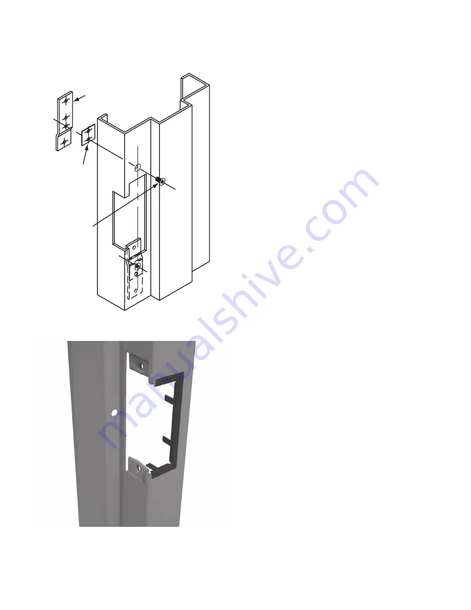
Frame

Self-Adhesive 

Mounting Shim (8 

incl.)

Mounting Tab

(2 incl.)

12-24 Machine 

Screws (2 per tab)

Mounting Tab Kit Instructions

Mounting tab kit is for use with aluminum and steel frames that 

do not have factory installed mounting tabs for electric strike 

installation.

1.  Prepare the frame as shown in the approximate 

drawing. Fasten the mounting tab to the faceplate 

of the strike, selecting the appropriate shims for the 

installation.

2.  Using the assembled strike and tabs as a template, 

place against the frame and mark the mounting hole 

locations. Remove and drill a 3/16” hole in frame for 

each mounting tab and countersink the frame.

3.  Remove the tabs from the faceplate and install in the 

frame using the 12-24 x 3/8” machine screws supplied. 

Tabs are zinc plated and drilled and tapped for this 

purpose.

4.  Make final electrical connections per wiring instructions 

and mount strike to the tabs with the 12-24 x 3/8” 

machine screws.

Trim Plate Instructions

1.  Position the Trim Plate on the frame cut-out to verify fit 

and coverage.

2.  Adjust cut-out if required.
3.  Bend the four tabs to hold the Trim Plate onto the 

frame.

4.  For a tighter fit, pre-bend the two long flange tabs 

before sliding onto the frame where space allows.

5.


Secure the strike to the frame as per strike installation 

instructions.

Summary of Contents for RCI 6 Series

Page 1: ... 7 8 4 875 123 83 C 3 3 8 3 375 85 73 D 1 3 16 1 188 30 16 E 3 8 375 9 53 F 1 8 125 3 18 G 1 11 16 1 688 42 86 Vertical Vertical Vertical X C L C L C L Door Door Door R 5 32 0 156 3 97 K 4 1 8 4 125 104 78 M 12 24 Vertical Centerline of Door E K B A F M G C G D R X C L C L M RCI L6504 Aluminum Frames 1 1 16 Insert Depth Modular AL65 with B604 faceplate MEASUREMENT FRACTIONAL INCHES DECIMAL INCHES ...

Page 2: ... 375 85 73 D 1 3 32 1 094 27 78 E 1 4 0 250 6 35 F 1 8 125 3 18 G 1 11 16 1 688 42 86 Vertical Vertical Vertical X C L C L C L Door Door Door R 5 32 156 3 97 K 5 3 8 5 375 136 53 M 12 24 Vertical Centerline of Door F C G G A M B K E X R D C L M C L RCI L6507 Aluminum Wood Frames 1 1 16 Insert Depth Modular AL65 with B607 faceplate A 1 1 4 1 250 31 75 B 6 7 8 6 875 174 63 C 3 3 8 3 375 85 73 D 1 3 ...

Page 3: ...DECIMAL INCHES METRIC mm A 1 7 16 1 438 36 51 B 7 15 16 7 938 201 61 C 3 3 8 3 375 85 73 D 1 3 16 1 188 30 16 E 1 4 0 250 6 35 F 1 8 125 3 18 G 1 11 16 1 688 42 86 Vertical Vertical Vertical X C L C L C L Door Door Door R 5 32 156 3 97 K 7 7 16 7 438 188 91 M 12 24 Vertical Centerline of Door X E K B R M D G G C A M RCI L6508 Aluminum Wood Frames 1 1 16 Insert Depth Modular AL65 with B608 faceplat...

Page 4: ...ace against the frame and mark the mounting hole locations Remove and drill a 3 16 hole in frame for each mounting tab and countersink the frame 3 Remove the tabs from the faceplate and install in the frame using the 12 24 x 3 8 machine screws supplied Tabs are zinc plated and drilled and tapped for this purpose 4 Make final electrical connections per wiring instructions and mount strike to the ta...

Page 5: ...ike Insert Keeper Fig 1 Fail Safe screw fully counter clockwise Fig 2 Fail Secure screw fully clockwise Fig 3 Lip bracket adjustment Wiring Instructions NOTE Overheated or Burnt Coils caused by incorrect input voltage wire harness combinations will not be covered under warranty For 12VDC or 12 24VAC input power connect RED and BLUE wires to positive connect BLACK and YELLOW wires to negative For 2...

Page 6: ...ge AC power supply and the 12V connector If this cannot be done a DC piezo buzzer can be installed Strike makes a buzzing sound Improper power supply Replace the power supply with a correct voltage DC power supply Insert has a burnt smell Improper voltage Confirm that you have the correct output voltage at the power supply Improper application A strike connected to an AC power supply will buzz unl...

Reviews: