64
ED50/ED100/ED250
09-2021
DL4617-003
dormakaba ED50/ED100/ED250 OHC Header
Setup and Troubleshooting Instructions
Appendix B
B.1 Information and error codes
Appendix B - Troubleshooting
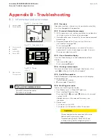
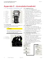
1
4 button keypad
2
2 digit display
Fig. B.1.1 User interface
3
Power switch
4
Red LED
5
Yellow LED
6
Green LED
Fig. B.1.2 Operator LEDs
Fig. B.1.3 Mode
switch
7
Mode switch,
Close position
B.1.1 Overview
Operator monitors internal circuits and external safety
circuits managed by the operator.
B.1.2 Error and information messages.
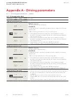
1. With operator in use, certain conditions may develop
resulting in error or information messages.
2. Operator attempts to identify the cause and respond
accordingly.
3. Response depends on the severity of the error:
• Information message (
ln
)
• Error message (
E
)
• Deactivating the operator's automatic function;
operator will switch to emergency mode. Users can
then access door manually.
B.1.3 User information display.
User interface display, or or dormakaba handheld
displays:
• Information
ln
codes
• Error message
E
codes
B.1.4 Viewing error messages.
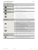
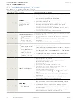
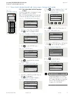
To access and view error messages, briefly press the
right
button on the 4 button keypad.
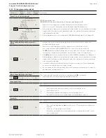
B.1.5 Red LED on operator
.
Red LED adjacent to operator power switch displays
blinking codes for:
• Certain
ln
information
• E
error codes (Para. B.2)
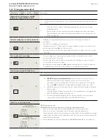
B.1.6 Resetting error codes.
Options for resetting error codes:
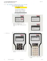
1. Set Mode switch in Close (off) position.
2. User interface Reset buttons:
• Press both left
and right
buttons >3s to reset
system (v1.8).
• Header cover must be opened to access user
interface.
3. Power reset:
• Turn power switch OFF.
• Turn power switch back on after 10 seconds.
CAUTION
Always analyze and remove cause for error
before resetting error message!
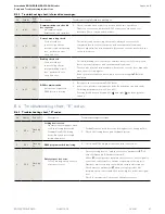
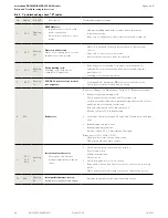
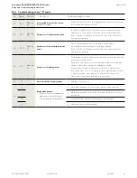
Troubleshooting charts (Para. B.3,.4) are
intended as a guide for diagnosing errors.
TIPS AND RECOMMENDATIONS
Para. B.3, Information codes
Para. B.4, Error codes
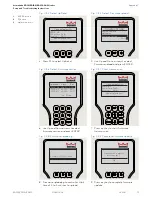
> 3s Reset
< 3s Quit
> 3s
PRG
< 3s
LEARN
Fact-Setup
> 3s
> 8s
1
2
4
5
6
3

