background image

FAL.OM.002372.DRM 

Page 54 of 62 

Version 1.6draft2 


Doremi Labs 


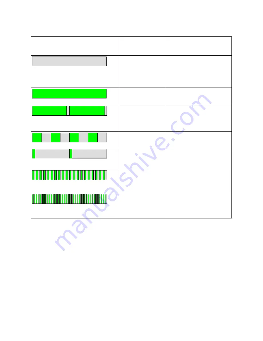
Receiver HI or VI LED 

(docked or undocked) 

Pattern 

Meaning 


Both Off 

The main receiver function of 
the device is turned off.  If 
docked, the processor is still 
powered up, for configurator 
commands. 


One LED steady on  Receiving audio correctly from 

a HI or VI broadcast channel. 


One LED on, with an 
'off' period every 2 
seconds 

Receiving correctly, but 
unable to find a clear radio 
channel to transmit status 
messages. 


One LED flashing 
once per second. 

Searching for a broadcast HI 
or VI channel. 


Both LEDs flash 
briefly every 2 
seconds 

No valid audio channel 
configured. 


Both LEDs flash 
rapidly, 5 times per 
second 

Incorrect configuration data, or 
radio uncalibrated. 


Both LEDs flash 
very rapidly, 10 
times per second 

In radio test mode. 


Summary of Contents for AccessLink

Page 1: ...k Device to Interface Non Doremi Cinema Servers with Fidelio and CaptiView Systems Installation User Manual Version 1 6draft3 The English version of this document is the only legally binding version Translated versions are not legally binding and are for convenience only ...

Page 2: ...2 3 2 Assigning the Transmitter Channel 24 3 2 1 Connections in Projection Booth 29 3 2 1 1 USB Power 29 3 3 Fidelio Audio Interface for Non Doremi Servers 29 3 3 1 Server to Audio Interface and then to Theater Sound Processor 29 3 3 1 1 DB25 Connector Setup 29 3 3 1 2 RJ45 Connector Setups 31 3 3 1 3 Audio Interface to AccessLink 32 4 Assigning the Fidelio Receiver to an Auditorium 34 5 CaptiView...

Page 3: ...Track Mapping 46 6 1 ISDCF Interop Specs 46 7 Digital Cinema Naming Convention 48 7 1 Appendix 4 Audio Configuration and Narrative Description Track Language 49 8 Technical Specifications 51 8 1 Fidelio System 51 8 2 AccessLink Transmitter 51 8 3 Fidelio Receiver 51 8 4 Ethernet Connection 51 9 LED Lights Description 53 9 1 Fidelio Receiver LEDs 53 9 2 AccessLink Transmitter Unit LEDs 55 10 Append...

Page 4: ...ement The software license agreement can be found at the following location http www doremilabs com support cinema support cinema warranties Hardware Warranty The hardware warranty can be found at the following location http www doremilabs com support cinema support cinema warranties ...

Page 5: ...r or qualified professional engineer to repair or re assemble the Fidelio with AccessLink Apart from voiding the warranty unauthorized engineers might touch live internal parts and receive a serious electric shock Do not put or allow anyone to put any object especially metal objects into the Fidelio with AccessLink Use only the provided AC power supply Never use a DC power supply If water or any o...

Page 6: ...the following two conditions 1 this device may not cause interference and 2 this device must accept any interference including interference that may cause undesired operation of the device Le présent appareil est conforme aux CNR d Industrie Canada applicables aux appareils radio exempts de licence L exploitation est autorisée aux deux conditions suivantes 1 l appareil ne doit pas produire de brou...

Page 7: ...smitter has been approved by Industry Canada to operate with the antenna type listed below with the maximum permissible gain indicated Antenna types not included in this list having a gain greater than the maximum gain indicated are strictly prohibited for use with this device Antenna Pulse Part Number SPDA24850 1900 Maximum Gain 3dB ...

Page 8: ...representation of a person within an equilateral triangle is intended to alert the user to the presence of uninsulated dangerous voltage within the product s enclosure that may be of sufficient magnitude to constitute a risk of electric shock The exclamation point within an equilateral triangle is intended to alert the user to the presence of important operating and maintenance servicing instructi...

Page 9: ...essLink System Parts AccessLink Transmitter Box Doremi P N ACCESSLINK AccessLink Transmitter Antenna Doremi P N FIDELIO TX ANT 2 meter USB cable A B Doremi P N CBL USBA USBB 6 Fidelio Audio Interface Box FIS o Doremi P N for Doremi Servers FIDELIO AI DB25 or RJ45 setups o Doremi P N for GDC FIDELIO AI DB25 or RJ45 setups o Doremi P N for Sony FIDELIO AI S DB25 only setups o Doremi P N for Dolby FI...

Page 10: ...dio Interface box 1 4 Contact If in need of help or assistance please contact Doremi Labs Technical Services USA 24 7 Technical Services line 1 866 484 4004 Technical Services Email cinemasupport doremilabs com Europe 24 7 Technical Services line 33 0 492 952 847 Technical Services Link http support doremitechno org ticketing Japan Technical Services line 044 966 4855 Technical Services Email supp...

Page 11: ...FAL OM 002372 DRM Page 11 of 62 Version 1 6draft2 Doremi Labs This page has been intentionally left blank ...

Page 12: ... their boxes Double check and confirm that all the parts and components are present 2 1 1 AccessLink Transmitter The AccessLink Transmitter is the device that will transmit the Hearing Impaired HI or Visually Impaired Narrative VI N audio track from the Digital Cinema Package DCP to the Fidelio Receiver You will need one AccessLink Transmitter for every auditorium you choose to enable Figure 1 Fig...

Page 13: ...he patron then takes the receiver into the assigned auditorium to receive the transmission from the AccessLink Transmitter Depending on the configuration assignment the receiver will either receive the HI audio track the VI N audio track or both the HI VI N audio tracks Figure 2 and Figure 3 Figure 2 Fidelio Receiver and Rear View Figure 3 Fidelio Receiver Top View and Side View Removable Belt Cli...

Page 14: ... Fidelio receivers The touchscreen tablet original tablet v1 1 2 Figure 4 is used to display the graphical user interface GUI when configuring each receiver Refer to Figure 5 for configuration charging station containing the latest version of the Fidelio tablet Figure 4 Fidelio Configuration Charging Station with Tablet v1 1 2 Figure 5 Fidelio Configuration Charging Station with Tablet v 2 2 0 ...

Page 15: ...harging Station and Tablet Figure 6 Fidelio Configuration Charging Station Side View Figure 7 Fidelio Configuration Charging Station Top View Figure 8 Fidelio Tablet v 1 1 2 Front View USB Hub Port Power Receptacle Receiver Charging Ports Receiver Configuration Port Tablet v 1 1 2 Home Button ...

Page 16: ...iew Figure 10 Fidelio Tablet v1 1 2 Side View Figure 11 Fidelio Tablet v2 2 0 Side View Mini USB Port Headphone Jack Not Used On Off Power Button MicroSD Card Port HDMI Port Not Used Volume Rocker On Off Power Button Headphone Jack Not Used HDMI Port Not Used Micro USB Port Charging Port Charging Port ...

Page 17: ... 2 1 5 Fidelio Audio Interface for Non Doremi Servers Figure 12 Fidelio Audio Interface FIS Front View Figure 13 Fidelio Audio Interface FIS Rear View DB25 Connector AES THRU Ch 1 6 Ch 9 14 Female BNC Connector AES OUT CH 15 16 Female BNC Connector AES OUT CH 7 8 ...

Page 18: ...FAL OM 002372 DRM Page 18 of 62 Version 1 6draft2 Doremi Labs This page has been intentionally left blank ...

Page 19: ...let bracket can hang down and sit flush with the bottom of the base Line up the four 4 holes of the tablet mounting bracket to the four 4 holes of the Charging Configuration Base Using a Phillips screwdriver carefully secure the Tablet Mounting Bracket to the Charging Configuration Base using the four 4 M3x6 Black Flat Head Machine Screws provided 3 1 2 Installation of Tablet into the Stand Bracke...

Page 20: ...ply cable into the port labeled Power on the Charging Configuration Base Figure 15 Figure 15 Power Port Plug the small end of the connector with the yellow tip into the touchscreen tablet port labeled DC IN 5V which is located on the right hand side of the touchscreen tablet v 1 1 2 Figure 16 v2 2 0 Figure 17 Tablet Clip Tightening Screws ...

Page 21: ...2 Power Connector Figure 17 Tablet v2 2 0 Power Connector Using a 4 Nylon black tie wrap provided slip the tie wrap though the eyelet Figure 18 to secure the cable to the tablet mounting bracket DC IN 5V Tablet Power Connector DC IN 5V Tablet Power Cable Micro USB Cable Micro USB Cable ...

Page 22: ...USB Cable Figure 19 USB Connectors Plug the large end Type B of the USB cable into the Fidelio configuration charging station base and the smaller end Type Mini B into the micro USB port located on the right hand side of the Fidelio touchscreen tablet Figure 19 and Figure 20 This USB Cable Tie Wrap Eyelet ...

Page 23: ...auditoriums along with their audio channel assignments Note The USB cable may actually be an A to B cable with an adapter to convert to a Mini B Micro USB cable Figure 20 Fidelio Charging Station and Tablet v1 1 2 Figure 21 Fidelio Charging Station and Tablet v2 2 0 USB Type B Cable USB Type Mini B Cable Micro USB Cable USB Type B Cable ...

Page 24: ...pe B of the USB cable into the Fidelio Transmitter and the smaller end Type Mini B into the micro USB port located on the right hand side of the Fidelio touchscreen tablet Figure 20 Power up the Fidelio touchscreen tablet by depressing the power switch Refer to the Figure 8 v1 1 2 and Figure 9 v2 2 0 for the location of the power button Note You will need to keep pressure on the switch until the A...

Page 25: ... unlocked you will be presented with the application icons screen Using your finger touch the Fidelio application icon to launch the application Figure 24 Fidelio Application Icon At first you will see a message saying Looking for Fidelio Devices Figure 25 Fidelio Application Icon Home Icon Unlock Padlock Icon ...

Page 26: ...Figure 25 Looking for Fidelio Devices Screen Once the Fidelio Transmitter is recognized a screen will appear that will indicate what auditorium number has been assigned to the transmitter Simply touch the Change button on the screen to change the auditorium assignment Figure 26 Figure 26 Transmitter Change Auditorium Screen ...

Page 27: ...mber press the Home button Refer to Figure 8 for v1 1 2 Refer to Figure 24 for v2 2 0 on the tablet and disconnect the USB cable connected to the transmitter Label the transmitter with the appropriate auditorium assignment as a reference so that it is installed in the correct projection booth To configure another transmitter launch the Fidelio application and connect the transmitter to the configu...

Page 28: ...ersion 1 6draft2 Doremi Labs Depress the Power Off selection and then press the OK button to complete the process Figure 29 v1 1 2 Figure 30 v2 2 0 Figure 29 Power Off OK Button Tablet v1 1 2 Figure 30 Power Off OK Button Tablet v2 2 0 ...

Page 29: ...Plugged into Fidelio Transmitter The other end of the Type A connector will need to be plugged into the USB Power Adapter provided Plug the USB Power Adapter into an AC outlet This connection will provide power to the AccessLink Transmitter 3 3 Fidelio Audio Interface for Non Doremi Servers The Fidelio Audio Interface box has the ability to interface with the DB25 connector and is used to access t...

Page 30: ...002372 DRM Page 30 of 62 Version 1 6draft2 Doremi Labs Using the short DB25 cable provided connect one end into the AES OUT on the server and the other end into the AES IN connector on the Audio Interface box ...

Page 31: ...ble to the connector that reads AES THRU CH 9 14 Figure 33 The other ends on these cables are to remain connected to your audio processor respectively Using the short RJ45 cable provided connect one cable into the CH 1 8 AES OUT on the server or IMB and the other end into the AES IN CH 1 8 connector on the Fidelio Audio Interface box Using the other short RJ45 cable provided connect one cable into...

Page 32: ...ed AES OUT CH 15 16 Connect the other end of this BNC cable to the AccessLink Transmitter box BNC connector labeled AES IN 2 Figure 34 Now connect another BNC cable NOT provided to the Audio Interface Box BNC connector labeled AES OUT CH 7 8 Connect the other end of this BNC cable to the AccessLink Transmitter box BNC connector labeled AES IN 1 Figure 34 Figure 34 AES Connection on Fidelio Transmi...

Page 33: ...FAL OM 002372 DRM Page 33 of 62 Version 1 6draft2 Doremi Labs This page has been intentionally left blank ...

Page 34: ...delio touchscreen tablet has finished booting up you will need to unlock the screen by using your finger on the unlock padlock icon and sliding up on the touch screen Figure 22 Once unlocked you will be presented with the Fidelio application icon screen Using your finger touch the Fidelio application icon to launch the application Figure 24 The tablet will display a message saying Looking for Fide...

Page 35: ...Fidelio Transmitter Figure 36 Figure 36 Receiver Auditorium Assignment Screen With your finger touch the theater number you wish to assign to the Fidelio receiver that is plugged into the Configuration Port The tablet will then display the Receiver screen Figure 37 Figure 37 Receiver Channel Assignment Screen When you select the Channel Change button you will be presented with the Select Channel s...

Page 36: ...tal Cinema Player s audio mapping will be configured similar to the recommendations in Figure 42 Selecting Ch 1a will provide the audio channel 7 in L R mono to the receiver Selecting Ch 2a will provide the audio channel 15 in L R mono to the receiver Selecting Ch 1b will provide the audio channel 8 in L R mono to the receiver Selecting Ch 2b will provide the audio channel 16 in L R mono to the re...

Page 37: ...FAL OM 002372 DRM Page 37 of 62 Version 1 6draft2 Doremi Labs This page has been intentionally left blank ...

Page 38: ...to complete the setup of the device 5 1 Items to Configure All the items mentioned below must be configured for a CaptiView to work properly on an AccessLink Figure 39 Figure 40 and Figure 41 Network configuration IP address Netmask Gateway Auditorium number Each auditorium in the theater must have its own auditorium number assigned to the CaptiView Transmitter Dongle Server s IP address The IP ad...

Page 39: ...AL OM 002372 DRM Page 39 of 62 Version 1 6draft2 Doremi Labs Figure 40 AccessLink Ethernet Port Figure 41 AccessLink Serial Port USB Connector Ethernet Port 5 Volt Power Supply ON OFF Switch Serial Port ...

Page 40: ... the following format Replace items in bold with your desired settings NTPSERVERS server1 ntp org server2 ntp org 6 Create a file and name it dns required for NTP with the following format Replace items in bold with your desired settings nameserver 172 17 16 1 nameserver 8 8 8 8 search rnd doremilabs fr domain rnd doremilabs fr Warning When creating these configuration files make sure that the fil...

Page 41: ...ine to your DNS type the following command echo nameserver 172 17 16 1 doremi etc resolv conf Enter 5 3 Configuring the Transmitter s Auditorium Number Note This is the only method valid for all AccessLink software versions For more information on logging into the Command Line Interface CLI see Section 5 5 To change the auditorium of the CaptiView Transmitter Dongle replace the bold item with a nu...

Page 42: ...e USB method use the IP address that was assigned to the AccessLink instead of the default IP When the unit is done booting up log in as root o Password for root veeone o It is recommended to change the root password by typing the following command and following the on screen instructions passwd 5 5 2 Logging into AccessLink via Serial Port The serial cable required for a proper connection is a fe...

Page 43: ...e folder doremi etc rc once and then reboot To check if the upgrade was successful open an SSH session and type the following command more doremi etc version and make sure that the version matches that of the pkg file 5 6 2 USB Flash Update 1 Create a directory name it doremi in the root of the USB flash drive 2 Inside the doremi directory create another folder and name it update e g doremi update...

Page 44: ...Enter The resulting file will be generated under tmp directory the operator will be able to use an FTP client to get it 5 7 2 Generating a Report via USB To generate a report using a USB key 1 Create a directory doremi at the root of the USB key might have been previously created 2 Create a directory report inside doremi directory 3 On the product remove the CaptiView Transmitter Dongle and plug i...

Page 45: ...FAL OM 002372 DRM Page 45 of 62 Version 1 6draft2 Doremi Labs This page has been intentionally left blank ...

Page 46: ...pecs Please refer to Figure 42 for the recommendations for use in all Interop DCP compositions Note The audio channel numbers for Interop DCP s map one to one to the audio outputs of a player For this reason the Table also identifies the recommended audio wiring in cinemas Figure 42 Interop ISDCF Recommendations ...

Page 47: ...FAL OM 002372 DRM Page 47 of 62 Version 1 6draft2 Doremi Labs This page has been intentionally left blank ...

Page 48: ...with the Digital Cinema Naming Convention which assists the operator with determining the technical components of the content Figure 43 The following will assist you in determining if a DCP has been mastered to include the Hearing Impaired HI and Visually Impaired Narrative VI N audio track s Figure 43 Digital Cinema Naming Convention v9 ...

Page 49: ...ersion 1 6draft2 Doremi Labs 7 1 Appendix 4 Audio Configuration and Narrative Description Track Language Note All other Appendix information referred to in Figure 43 and Section 7 1 can be found at www digitalcinemanamingconvention com ...

Page 50: ...FAL OM 002372 DRM Page 50 of 62 Version 1 6draft2 Doremi Labs This page has been intentionally left blank ...

Page 51: ...stereo channels per transmitter 2 Maximum number of receivers per transmitter 200 Power supply USB B socket Maximum current 500mA from 5V supply 8 3 Fidelio Receiver Format Box with several buttons miniature stereo jack User controls Volume up and down buttons User indicators 3LEDs indicating charging power on channel selection Number of channels selectable via configuration At least 20 auditoria ...

Page 52: ...FAL OM 002372 DRM Page 52 of 62 Version 1 6draft2 Doremi Labs This page has been unintentionally left blank ...

Page 53: ...nal power present While undocked the LEDs will be lit dimly for use in a dark cinema auditorium While docked the LEDs will be continuously lit See the tables below for more information Receiver Power LED while docked Pattern Meaning Steady On Battery charged more than 80 full Slow flash once every 2 seconds Battery is charging Receiver Power LED while undocked Pattern Meaning Off Device is turned ...

Page 54: ...orrectly from a HI or VI broadcast channel One LED on with an off period every 2 seconds Receiving correctly but unable to find a clear radio channel to transmit status messages One LED flashing once per second Searching for a broadcast HI or VI channel Both LEDs flash briefly every 2 seconds No valid audio channel configured Both LEDs flash rapidly 5 times per second Incorrect configuration data ...

Page 55: ...LED each channel Pattern Meaning Steady On AES3 input present and transmitting beacon or audio correctly Brief flash every 2 seconds No AES3 input connected not transmitting Flashing once per second Unable to transmit cannot find a clear channel due to radio band congestion Flashing rapidly 5 times per second Incorrect configuration data or radio uncalibrated or on the Slave channel not synchroniz...

Page 56: ...FAL OM 002372 DRM Page 56 of 62 Version 1 6draft2 Doremi Labs This page has been intentionally left blank ...

Page 57: ...FAL OM 002372 DRM Page 57 of 62 Version 1 6draft2 Doremi Labs 10 Appendix A Wiring Guide ...

Page 58: ...FAL OM 002372 DRM Page 58 of 62 Version 1 6draft2 Doremi Labs ...

Page 59: ...FAL OM 002372 DRM Page 59 of 62 Version 1 6draft2 Doremi Labs This page has been intentionally left blank ...

Page 60: ...Doremi Labs 11 Acronyms Term Definition AES Audio Engineering Society DB25 D Sub Miniature DCP Digital Cinema Package GUI Graphical User Interface HI Hearing Impaired IMB Integrated Media Block LED Light Emitting Diode VI N Visually Impaired Narrative ...

Page 61: ...FAL OM 002372 DRM Page 61 of 62 Version 1 6draft2 Doremi Labs This page has been intentionally left blank ...

Page 62: ...013 1 2 Section 10 added and Section 1 2 updated 05 14 2013 1 3 Section 8 1 and 1 2 updated and Section 3 3 1 2 added 04 24 2014 1 4 Minor edits made Added new image for Digital Cinema Naming Convention in Section 7 05 04 2014 1 5 Document updated to include new Fidelio tablet v2 2 0 The DCP naming convention version updated Minor editorial changes 10 30 2014 1 6draft3 Preface revised ...

Reviews: