background image

When replacing brake cables it is necessary to
adjust the brake shoes before adjusting the parking
brake system. To adjust the shoes, remove the
rubber hole plug in the brake backing plate and
rotate the star adjusting nut until you cannot rotate
the wheel by hand. Then back off the adjustment ten
to twelve (10--12) notches. Note: always rotate
wheel in direction of forward travel only. Replace
hole plug and proceed to next wheel and repeat
procedure.

Adjust parking brakes after all brake shoes have
been adjusted by:

1. Turning knob on brake lever until lever is
perpendicular to bracket when in “OFF” position.
Wheels should turn freely.

2. With lever in “OFF” position, adjust brake cables
until each has approximately the same tension.
Wheels should turn freely.

3. Move lever to “ON” position. Check each wheel
to see that it will not rotate. If all wheels will rotate,
adjust knob on lever until brakes are fully applied. If
one or two wheels will still rotate, adjust the cables
for those wheels and recheck.

4. After brakes are adjusted, move lever to “ON”
position and apply grease to cable strands from
conduit six inches toward lever. This is to prevent dirt
from getting into the conduit.

NOTE:

New cables will stretch and therefore should

be readjusted after the first week of use.

Every six months, apply a multi--purpose grease to
the fittings on the brake actuator.

Electric Brake Adjustment:

Brakes should be adjusted (1) after the first 200
miles of operation when the brake shoes and drums
have “seated”, (2) at 3000 mile intervals, (3) or as
use and performance requires. The brakes should
be adjusted in the following manner:

1. Jack up trailer and secure on adequate capacity
jack stands. Check that the wheel and drum rotate
freely.

2. Remove the adjusting hole cover from the
adjusting slot on the bottom of the brake backing
plate.

3. With a screwdriver or standard adjusting tool,
rotate the starwheel of the adjuster assembly to
expand the brake shoes. Adjust the brake shoes out
until the pressure of the linings against the drum
makes the wheel very difficult to turn.

4. Then rotate the starwheel in the opposite
direction until the wheel turns freely with a slight
lining drag.

5. Replace the adjusting hole cover and lower the
wheel to the ground.

6. Repeat above procedures on all brakes.

OIL SEPARATOR ELEMENT

The life of the oil separator element is dependent
upon the operating environment (soot, dust, etc.)
and should be replaced every twelve months or
2000 hours. To replace the element proceed as
follows:

* Ensure the tank pressure is zero.

* Disconnect the hose from the scavenge tube.

* Remove scavenge tube from tank cover.

* Disconnect service line from cover.

* Remove (16) cover mounting screws.

* Remove cover, element and inner shell.

* Remove any gasket material left on cover or tank.

* Install new gasket, inner shell and new element.

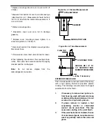
* Place a straightedge across top of element and
measure from bottom of straightedge to bottom of
element (See Fig. 4.1).

Summary of Contents for XHP1070WCAT-EX-T1

Page 1: ...anPortablePower com Book 46676805 4 2015 Rev A This manual contains important safety information Do not destroy this manual This manual must be available to the personnel who operate and maintain this compressor OPERATION MAINTENANCE MANUAL COMPRESSOR MODEL XHP1070WCAT EX T1 F62 ...

Page 2: ...rietary identifying marks belonging to Ingersoll Rand Company in this manual is historical and nominative in nature and is not meant to imply or suggest any current affiliation between Ingersoll Rand Company and Doosan Infracore Portable Power or the products of either Doosan Infracore Portable Power 1293 Glenway Drive Statesville N C 28625 DoosanPortablePower com DISCLAIMER ...

Page 3: ...CALIFORNIA Proposition 65 Warning Diesel engine exhaust and some of its constituents are known to the State of California to cause cancer birth defects and other reproductive harm ...

Page 4: ...nager 28 Issued at Statesville N C 29 30 The technical documentation for the machinery is available from CPN 46553504 Rev A exempt from Noise Emission Directive 2000 14 EC Doosan Infracore Portable Power 1293 Glenway Drive Statesville N C 28625Ͳ9218 USA Original declaration Date XHP1000WCATͲT4i 10 370 10 455 25 300 25 330 10 425 10 375 25 280 HP1600WCU T4i XHP1000WCATͲT4i 10 370 10 455 25 300 25 3...

Page 5: ... of a type approved by Portable Power clearly rated for a pressure at least equal to the compressor safety valve setting compatible with the compressor oil accompanied with instructions for safe installation operation and maintenance Details of approved equipment are available from the Portable Power Service departments The use of repair parts other than those included within the approved parts li...

Page 6: ...nce requirements explained in this manual be performed at the required intervals Exceeding these intervals may reduce the reliability of the compressor The purpose of this manual is to train the operator with functions operation and basic service and maintenance requirements of the compressor During the preparation of this manual every effort was made to ensure the accuracy and adequacy of the con...

Page 7: ...TABLE OF CONTENTS SECTION 1 SAFETY SECTION 2 NOISE EMISSION SECTION 3 GENERAL DATA SECTION 4 OPERATING INSTRUCTIONS SECTION 5 MAINTENANCE SECTION 6 LUBRICATION SECTION 7 TROUBLESHOOTING ...

Page 8: ...ffective check valves and isolation valves must be fitted and controlled by work procedures so that one machine cannot accidentally be pressurized or over pressurized by another Compressed air must not be used for a feed to any form of breathing apparatus or mask The discharged air contains a very small percentage of compressor lubricating oil and care should be taken to ensure that downstream equ...

Page 9: ...Do not open radiator while hot Rotating fan blade can cause serious injury Do not operate without guard in place Use care to avoid contacting hot surfaces engine exhaust manifold and piping air receiver and air discharge piping etc Ether is an extremely volatile highly flammable gas USE SPARINGLY Do NOT use ETHER if unit has GLOW Plug starting aid Engine damage will result Never allow the unit to ...

Page 10: ...ammable liquid Air gas flow or Air discharge Look for these signs onmachines shippedtointernationalmarkets outside NorthAmerica whichpoint out potential hazards to the safety of you and others Read and understand thoroughly Heed warnings and follow instructions If you do not understand inform you supervisor handbrake and wheel chocks Diesel Fuel No open flame Do not breathe the compressed air from...

Page 11: ... Service Designation Wet Location Operation WARNING Consult the operation and maintenance manual before performing any maintenance WARNING Before connecting the tow bar or when preparing to tow consult the operation and maintenance manual Replace any cracked protective shield On power Off power Emergency stop Do not use fork lift truck from this side Do not stack Do not operate with the doors or e...

Page 12: ...nance manual before operation or maintenance of this machine is undertaken XX km h Pressurized component or system Do not exceed the speed limit Pressurized vessel Do not remove the Operating and Maintenance manual and manual holder from this machine Use fork lift truck from this side only 0_C WARNING For operating temperature below 0_C consult the operation and maintenance manual ...

Page 13: ... which point out potential hazards to the safety of you and others Read and understand thoroughly Heed warnings and follow instructions If you do not understand inform you supervisor Air discharged from this machine can contain carbon monoxide or other contaminants which will cause serious injury or death Do not breathe this air DANGER Hot pressurized fluid Can cause serious burns Do not open radi...

Page 14: ...ation of this machine CAN cause serious injury or death Do NOT alter or modify this machine without the express written consent of the manufacturer WARNING WARNING WARNING WARNING Falling off machine CAN cause serious injury or death Access Lifting Bail from inside machine Rotating Fan Blade CAN cause serious injury Do NOT operate with guard removed Excessive Towing Speed CAN cause serious injury ...

Page 15: ...pressor s parts manual Submit orders for Safety Decals to the Statesville Parts Service Department The no charge order should contain only Safety Decals Help promote product safety Assure that decals are present on the machines Replace decals that are not readable FREE SAFETY DECALS Disconnected Air Hoses Whip CAN cause serious injury or death When using air tools attach safety device OSHA Valve a...

Page 16: ...take system or parts thereof c enclosure or parts thereof 2 Removal of any of the following a fan shroud b vibration mounts c sound absorption material 3 Operation of the compressor with any of the enclosure doors open Compressor Noise Emission Control Information A The removal or rendering inoperative other than for the purpose of maintenance repair or replacement of any noise control device or e...

Page 17: ...s to the ultimate purchaser and each subsequent purchaser that this air compressor was designed built and equipped to conform at the time of sale to the first retail purchaser with all applicable U S EPA Noise Control Regulations This warranty is not limited to any particular part component or system of the air compressor Defects in the de sign assembly or in any part component or system of the co...

Page 18: ...anels Enclosure panels should also be inspected at 100 hour operational intervals All panels that are warped punctured torn or otherwise deformed such that their noise containment function is reduced should be re paired or replaced before the next operation interval Doors access panels and hatch closures especially should be checked and adjusted at this time to insure continuous seating between ga...

Page 19: ...MAINTENANCE RECORD FOR NOISE EMISSION CONTROL AND EXTENDED WARRANTY ITEM NO DESCRIPTION OF WORK HOURMETER READING MAINT INSPECT DATE LOCATION CITY STATE WORK DONE BY NAME ...

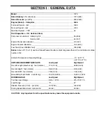
Page 20: ...el with sulfur content not greater than 0 5 and minimum cetane number of 42 Ambient Temperature Operating Range 10_ to117_F 23_C to 47_C UNITS MEASUREMENTS WEIGHTS Low Speed High Speed Overall Length drawbar up feet meters 17 0 5 18 22 83 6 96 Overall Height feet meters 8 46 2 58 8 53 2 60 Overall Width feet meters 7 38 2 25 7 38 2 25 GrossnWeight all fluids pounds kg 15 200 6 900 16 600 7 523 RUN...

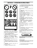
Page 21: ... those within gauges 12 Heaters Switch Activates control system heaters for operation below 32 F 0 C 13 Service Air Button After warm up provides full air pressure at the service outlet 14 Bypass Button Bypasses automatic shutdown circuit 15 Start Button Activates the engine starter 16 Ether Inject Button Injects a measured shot USE SPARINGLY DIAGNOSTICS AUTOMATIC SHUTDOWN 17 High Compressor Tempe...

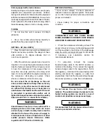
Page 22: ...safety hazard could occur in a back flow condition WARNING Unrestricted air flow from a hose will result in a whipping motion of the hose which can cause serious injury or death A safety device must be attached to the hose at the source of supply to reduce pressure in case of hose failure or other sudden pressure release Reference OSHA regulation 29 CFR Section 1926 302 b BEFORE STARTING Open serv...

Page 23: ...diagnostics lamps will light glow for two 2 seconds Then all lamps should go off except for ALTERNATOR NOT CHARGING and LOW ENGINE OIL PRESSURE In freezing weather below 32 F 0 C flip HEATERS switch On and wait sixty 60 seconds This applies heat to the control system components for easier starting Leave this switch On while operating at these temperatures Press and hold the BYPASS button for ten 1...

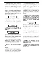
Page 24: ...m CAUTION Never allow the unit to sit stopped with pressure in the receiver separator system As a precaution open the service valve WARNING Even after pressure is relieved from the receiver separator system any air supply line from the compressor to a tool or machine could remain under pressure and cause very serious personal injury or death After the compressor stops carefully open a valve at any...

Page 25: ...stment is lost proceed as follows Before Starting Unit 1 WITH UNIT STOPPED disconnect rod end bearing on governor cable GC at engine governor lever 2 At bracket A near butterfly valve BV run nut B back on governor cable housing Push governor cable housing toward lever C Tighten nut D 3 Loosen screw J on lever C 4 Loosen nut E to relax spring G 5 Loosen nut H Turn rod L in Air Cylinder AC until app...

Page 26: ... at a time until steady tighten locknut H 16 Open service air valve and observe full load engine speed Adjust regulator to give rated operating pressure Tighten locknut M 17 Close and slowly open service air valve If engine speed surges increase tension on spring G by moving nuts E and F XHP900 Units ONLY Should not be adjusted by moving nuts E and F See Step 7 If set speeds are not correct repeat...

Page 27: ...he optimum operating level is midway of the sight tube on the side of the receiver tank See the decal beside the sight tube If the oil level is not in the OK range make appropriate corrections Add or Drain A totally filled sight tube in which the level is not visible indicates an over full condition and requires that oil be drained COMPRESSOR OIL This machine was factory filled with ProTecR Compre...

Page 28: ...ators to be ineffective The air filters restricted sensor will automatically reset after the main power switch is flipped to OFF To service the air cleaners on all units proceed as follows 1 Loosen outer wing nut and remove with outer element Inspect red window on special inner wing nut to find small dot If dot is not visible remove cotter pin and special wing nut and inner safety element 2 Inspec...

Page 29: ...six months the drain plugs should be removed from the tanks so that any sediment or accumulated condensate may be drained When replacing the drain plugs make sure they are tightened securely BATTERY Heavy duty diesel cranking type batteries were installed at the factory and these should be inspected weekly Keep the battery posts to cable connections clean tight and lightly coated with a grease Als...

Page 30: ... of pressure from a heated cooling system can result in serious personal injury The engine cooling system is filled at the factory with a 50 50 mixture of water and ethylene glycol This permanent type antifreeze contains rust inhibitors and provides protection to 35 F 37 C The use of such a mixture is recommended for both summer and winter operation When using water alone be sure to add a reputabl...

Page 31: ...rication and cooling oil system includes dual spin on throw away type oil filters each with an internal bypass valve With a clean new filter element all of the oil flows through the full element area from the outside inside As each elementbecomes contaminated withdirt apressure differential is created in the filter housing between the oil inlet and outlet ports As this differential approaches 25 p...

Page 32: ...eratures Grease can be replaced in a wheel bearing using a special fixture or by hand as follows Place a spoonful of grease in the palm of one hand and take the bearing in the other hand Push a segment of the wider end of the bearing down into the outer edge of the grease pile closest to the thumb Keep lifting and pushing the bearing down into the edge of the grease pile until grease oozes out bot...

Page 33: ...the receiver separator tank cover and terminates at the compressor airend through an orifice Once a year or every 2000 hours of operation whichever comes first remove this line and any orifice thoroughly clean then reassemble NOTICE Excessive oil carry over may be caused by an oil logged separator element Do not replace element without first performing the following maintenance procedure 1 Check o...

Page 34: ...ric Brake Adjustment Brakes should be adjusted 1 after the first 200 miles of operation when the brake shoes and drums have seated 2 at 3000 mile intervals 3 or as use and performance requires The brakes should be adjusted in the following manner 1 Jack up trailer and secure on adequate capacity jack stands Check that the wheel and drum rotate freely 2 Remove the adjusting hole cover from the adju...

Page 35: ...gasket connection Figure No 4 1 Element Measurement STRAIGHTEDGE ELEMENT SEPARATOR TANK Figure No 4 2 Tube Measurement TANK TOP SCAVENGE TUBE SHOULD BE 1 8 TO 1 4 SHORTER THAN ELEMENT MEASURED cut line if necessary EXTERIOR FINISH CARE This unit was painted and heat cured at the factory with a high quality thermoset polyester powder coating The following care will ensure the longest possible life ...

Page 36: ...e primer to splatter causing the textured look Note you must be careful not to put too much primer on at one time this will effect the amount of texture that you are trying to achieve Allow the texture coat to flash for 20 minutes or until dry to touch 10 Apply any of Duponts Topcoat Finishes such as Imront or Centarit according to the label instructions Note To re topcoat the textured surfaces wh...

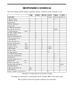
Page 37: ...s C Hoses oil air intake etc C Automatic Shutdown System Test C Air Cleaner System Visual C Compressor Oil Cooler Exterior C CLEAN Engine Radiator Exterior C CLEAN Fasteners Guards C Air Cleaner Elements WI Fuel Water Separator Element R Compressor Oil Filter Element R Compressor Oil R Wheels bearings seals etc C C Engine Coolant Test C R Shutdown Switch Settings Test C Scavenge Orifice related pa...

Page 38: ...ich may be insoluble Such deposits can cause se rious troubles including clogging of the filters Where possible do NOT mix oils of different types and avoid mixing differentbrands Atype or brand change is best made at the time of a complete oil drain and refill If the unit has been operated for the time hours men tioned above it should be completely drained of oil If the unit has been operated und...

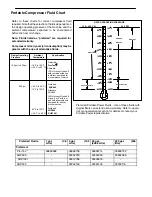
Page 39: ...pressor Fluid Chart 23_C to 52_C 10_F to 125_F Pro Tect XHP 605 10_F to 125_F 23_C to 52_C 65_F to 125_F XHP1001 Preferred Portable Power Fluids Use of these fluids with original filters can extend airend warranty Refer to opera tor s manual warranty section for details or contact your Portable Power representative XHP405 18_C to 52_C XHP605 Alternate XHP405 Preferred Preferred Alternate Preferred...

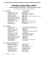
Page 40: ...or will still operate is it safe to continue operating it to make further checks B Do The Simplest Things First Most troubles are simple and easily corrected For example most complaints are low capacity which may be caused by too low an engine speed or compressor over heats which may be caused by low oil level Always check the easiest and most obvious things first following this simple rule will s...

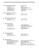
Page 41: ...g Air Loose Wire Connection Malfunctioning circuit board TROUBLE SHOOTING CHART Bold Headings depict the COMPLAINT Subheadings suggest the CAUSE Note Subheadings suggest sequence to follow troubleshooting Add CLEAN diesel Fuel See Complaint 10 Check coolant level If necessary Add See Complaint 3 and Complaint 4 Replace fan belt Wiggle wires at switches connector blocks Make repairs Replace switch ...

Page 42: ...nctioning Relay Defective Safety Bypass Switch Add oil Relocate or reposition See Engine Oil Spec Change oil Replace element s See Trouble Shooting in Engine Manual Repair or replace Replace circuit Replace circuit board Replace circuit board Replace circuit board Replace circuit board Tighten or replace belt set Repair or replace connection Check electrolyte level Add if necessary Check connector...

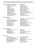
Page 43: ...nimum Pressure Valve Defective Separator Element Wrong Air Filter Element Above spec limit Relocate or reposition unit Add oil Look for any leaks Check spec in this manual Clean exterior surfaces Move unit to cleaner environment Replace elements Change oil Tighten or replace belt set Reduce pressure to spec Close side doors Replace belly pan Replace thermostat in bypass valve Check fan belt tensio...

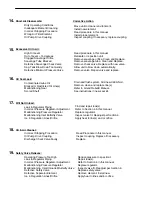
Page 44: ...tterfly Valve Defective Safety Valve Defective Separator Element Ice in Regulation Lines Orifice Move unit to cleaner environment Install new element Read procedure in this manual Install proper element Inspect coupling If necessary replace coupling Read procedure in this manual Relocate or reposition unit Remove scavenge orifice Clean and Replace Remove scavenge tube Clean and Replace Remove chec...

Page 45: ...Revision History Rev EC Number Comments A Original release ...

Page 46: ... Doosan Infracore Portable Power Printed in the U S A Doosan Infracore Portable Power 1293 Glenway Drive Statesville N C 28625 www doosanportablepower com ...

Reviews: