MAINTENANCE
34
7/20, P65
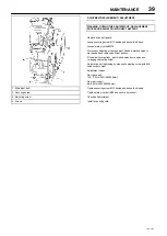
SCAVENGE LINE
The scavenge line runs from the combined orifice/drop tube in the
separator tank, to the orifice fitting located in the airend.
Examine the orifice, check valve and hoses at every service or in
the event of oil carryover into the discharge air.
It is good preventative maintenance to check that the scavenge line
and tube are clear of any obstruction each time the compressor
lubricant is changed as any blockage will result in oil carryover into the
discharge air.
COMPRESSOR OIL FILTER
Refer to the
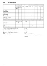
MAINTENANCE CHART
in this section for the
recommended servicing intervals.
Removal
WARNING: Do not remove the filter(s) without first making sure
that the machine is stopped and the system has been completely
relieved of all air pressure.
(Refer to
STOPPING THE UNIT
in the
OPERATING INSTRUCTIONS
section of this manual).
Clean the exterior of the filter housing and remove the
spin
−
on
element by turning it in a counter
−
clockwise direction.
Inspection
Examine the filter element.
CAUTION:
If there is any indication of the formation of varnishes,
shellacs or lacquers on the filter element, it is a warning that the
compressor lubricating and cooling oil has deteriorated and that it
should be changed immediately. Refer to LUBRICATION later in this
section.
Reassembly
Clean the filter gasket contact area and install the new element by
screwing in a clockwise direction until the gasket makes contact with
the filter housing. Tighten a further
1
/
2
to
3
/
4
of a revolution.
CAUTION:
Start the machine (refer to PRIOR TO STARTING and
STARTING THE UNIT in the OPERATING INSTRUCTIONS section
of this manual) and check for leakage before the machine is put back
into service.
COMPRESSOR OIL SEPARATOR ELEMENT
Normally the separator element will not require periodic
maintenance provided that the air and oil filter elements are correctly
maintained.
If, however, the element has to be replaced, then proceed as
follows:
Removal
WARNING: Do not remove the filter(s) without first making sure
that the machine is stopped and the system has been completely
relieved of all air pressure.
(Refer to
STOPPING THE UNIT
in the
OPERATING INSTRUCTIONS
section of this manual).
Disconnect all hoses and tubes from the separator tank cover plate.
Remove the drop
−
tube from the separator tank cover plate and then
remove the cover plate. Remove the separator element.
Inspection
Examine the filter element. Examine all hoses and tubes, and
replace if necessary.
Reassembly
Thoroughly clean the orifice/drop tube and filter gasket contact area
before reassembly. Install the new element.
WARNING
Do not remove the staple from the anti
−
static gasket on the
separator element since it serves to ground any possible static
build
−
up.
Do not use gasket sealant since this will affect electrical
conductance.
Reposition the cover plate, taking care not to damage the gasket,
and replace the cover plate screws tightening in a
criss
−
cross
pattern
to the recommended torque (refer to the
TORQUE SETTING TABLE
later in this section).
Engage the adaptor in the cover plate with the drop
−
tube integral
with the filter, reconnect all hoses and tubes to the separator tank cover
plate.
Replace the compressor oil (refer to
LUBRICATION
later in this
section).
CAUTION:
Start the machine (refer to PRIOR TO STARTING and
STARTING THE UNIT in the OPERATING INSTRUCTIONS section
of this manual) and check for leakage before the machine is put back
into service.

