


OP001015
4-83
Inspection, Maintenance and Adjustment
PARKING BRAKE ADJUSTMENT
To adjust parking brake, perform the following steps:
1.
Jack up machine enough to allow tires to rotate freely.
Turn “OFF” engine and place transmission lever in “NEUTRAL.”
Turn ignition switch to “ON” position. Move parking brake switch
to “UNLOCKED” position.
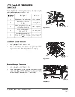
Front Axle Service Brakes
Checking clearance between brake pad and brake disc in the
front axle.
1.
Locate the pinion adjusting bolt in the upper part of the
differential housing.
2.
Remove lock bolt (2, Figure 118) and bracket (1).
3.
Rotate the square pinion adjusting bolt (3, Figure 118) in
counter clockwise direction until it stops. At this time the
clearance of brake disk is “0”.
4.
Rotate adjusting bolt (3, Figure 118) clockwise four turns (0.25
mm / rotation) to set the clearance to 1 mm (0.4 in).
5.
Install lock bracket (1, Figure 118) and bolt (2).
Repeat steps 1-5 for other side.
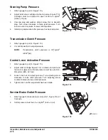
Front Axle Parking Brake Emergency
Release
1.
Locate parking brake release bolt on the lower section on
both sides of the housing.
2.
Loosen lock nut (4, Figure 118) from adjusting bolt (5).
3.
Tighten adjusting bolt (5, Figure 118) until it stops. This will
manually release the parking brake so that the drive shaft
will be free to turn.
The initial setting of adjusting bolt is 47 mm and should be
readjusted to this length and lock nut tightened after towing is
complete.
Rear Axle Service Brake
There are three adjusting bolts per side at 120° intervals for the
rear axle brake adjustment. All three must be adjusted for proper
operation. The adjusting procedure is same as the front brake
adjustment method and must be repeated for both sides.
Figure 118
Summary of Contents for DL220
Page 2: ......
Page 6: ...950106 00117E Table of Contents IV ...
Page 7: ...950106 00117E I I Presentation 1Presentation PRESENTATION FG015573 Figure 1 ...
Page 17: ...OP001012 1 5 Safety 1 3 12 6 4 11 5 9 10 8 3 7 10 9 4 6 2 FG015631 Figure 1 ...
Page 62: ...OP001012 Safety 1 50 ...
Page 112: ...OP001013 Operating Controls 2 50 CD Player Optional AST DIR FG000109 Figure 102 ...
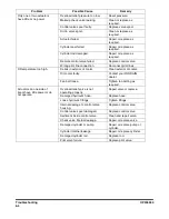
Page 240: ...OP000040 Troubleshooting 6 8 ...


