


OP001015
4-77
Inspection, Maintenance and Adjustment
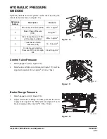
HYDRAULIC PRESSURE
CHECKS
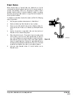
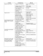
Hydraulic pressure for most systems can be check by using the
remote test ports shown in (Figure 110).
Control Valve Pressure
1.
Attach gauge to port (1, Figure 110).
2.
Relief valve cartridge on control valve (Figure 111) must be
adjusted to open at 200 ± 5 kg/cm
2
(2,844 ± 70psi)
Brake Charge Pressure
1.
Attach gauge to port (2, Figure 110).
2.
Adjust relief valve cartridge on brake, pilot and fan motor
supply valve (Figure 112). Relief pressure (Figure 112) for
brake charging is 80 ± 5 kg/cm
2
(1,138 ± 70 psi).
1
3
2
4
5
FG015619
Figure 110
Reference
Number
Description
Pressure
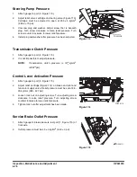
1
Main Pump Pressure (TPM)
210 ± 5 kg/cm
2
2
Brake Charge Pressure
(TP2)
80 kg/cm
2
3
Steer Pump Pressure (TPS)
at Only Steering Relief
200 ± 5 kg/cm
2
4
Transmission Clutch
Pressure (TM)
16 - 18 kg/cm
2
5
Control Lever Activation
Pressure (TP1) at E/G High
Idle
28 +2/-0 kg/cm
2
FG008107
Figure 111
FG008108
Figure 112
Summary of Contents for DL220
Page 2: ......
Page 6: ...950106 00117E Table of Contents IV ...
Page 7: ...950106 00117E I I Presentation 1Presentation PRESENTATION FG015573 Figure 1 ...
Page 17: ...OP001012 1 5 Safety 1 3 12 6 4 11 5 9 10 8 3 7 10 9 4 6 2 FG015631 Figure 1 ...
Page 62: ...OP001012 Safety 1 50 ...
Page 112: ...OP001013 Operating Controls 2 50 CD Player Optional AST DIR FG000109 Figure 102 ...
Page 240: ...OP000040 Troubleshooting 6 8 ...


