background image

3

FOREWORD

Summary of Contents for D82

Page 1: ...Portable Power 1293 Glenway Drive Statesville N C 28625 DoosanPortablePower com P N 46553446 9 2013 Rev C This manual contains important safety information Do not destroy this manual This manual must...

Page 2: ...2...

Page 3: ...achines distributed within the United States 2 22 Noise Emission Warranty 2 23 Introduction 2 23 GENERAL DATA 4 27 General Data 4 28 Unit Model 4 28 Fluid Capacities 4 28 Running Gear 4 28 Unit Measur...

Page 4: ...6 45 Fuel Tank 6 45 Battery 6 45 Fasteners 6 46 Radiator 6 46 Hoses 6 46 Compressor Oil Cooler 6 48 Compressor Oil 6 48 Receiver Separator Systems 6 49 Scavenge Line 6 50 Exterior Finish Care 6 50 MAI...

Page 5: ...3 FOREWORD...

Page 6: ...ble be of a type approved by Portable Power clearly rated for a pressure at least equal to the compressor safety valve setting compatible with the compressor oil accompanied with instructions for safe...

Page 7: ...requirements explained in this manual be performed at the required intervals Exceeding these intervals may reduce the reliability of the compressor The purpose of this manual is to train the operator...

Page 8: ...Operation Maintenance Manual FOREWORD 6...

Page 9: ...7 DRAWBAR NOTICE...

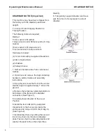
Page 10: ...2 Open box and remove the bag containing hardware safety chains and assembly instructions 3 Using the jack raise the front of the unit so that the legs are approximately 1 above the ground 4 Remove th...

Page 11: ...DRAWBAR NOTICE Operating Maintenance Manual 9...

Page 12: ...Operating Maintenance Manual DRAWBAR NOTICE 10...

Page 13: ...11 SAFETY...

Page 14: ...cannot be started accidentally Ensure that the machine is operating at the rated pressure and that the rated pressure is known to all relevant personnel All air pressure equipment installed in or conn...

Page 15: ...loss Always wear hearing protection when doors are open or service valve is vented Never inspect or service unit without first disconnecting battery cable s to prevent accidental starting Do not remo...

Page 16: ...Operating Maintenance Manual SAFETY 14...

Page 17: ...ow back into the compressor system from devices or systems downstream of the machine unless the service valve is closed Install a check valve at the machine service valve to prevent reverse flow in th...

Page 18: ...Operating Maintenance Manual SAFETY 16...

Page 19: ...SAFETY Operating Maintenance Manual 17...

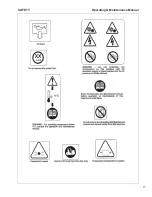
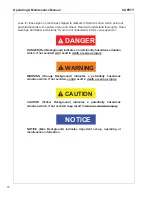
Page 20: ...DANGER Red Background indicates an imminently hazardous situation which if not avoided will result in death or serious injury WARNING WARNING Orange Background indicates a potentially hazardous situa...

Page 21: ...SAFETY Operating Maintenance Manual 19...

Page 22: ...ER WARNING or CAUTION Decal part numbers are on the bottom of each decal and are also listed in the compressor s parts manual Submit orders for Safety Decals to the Portable Power Parts Service Depart...

Page 23: ...21 NOISE EMISSION...

Page 24: ...s thereof b the air intake system or parts thereof c enclosure or parts thereof 4 Removal of any of the following a fan shroud b vibration mounts c sound absorption material 5 Operation of the compres...

Page 25: ...ent or system of the air compressor Defects in the design assembly or in any part component or system of the compressor which at the time of sale to the first retail purchaser caused noise emissions t...

Page 26: ...prevent subsequent damage and noise emission increase E Enclosure Panels Enclosure panels should also be inspected at 100 hour operational intervals All panels that are warped punctured torn or other...

Page 27: ...each 250 hours of operation Those mounts with cracks or splits in the molded rubber or with bent or broken bolts due to operation or storage in severe environments all should be replaced with equival...

Page 28: ...Maintenance Manual NOISE EMISSION 26 Maintenance Record For Noise Emission Control And Extended Warranty Item No Description Of Work Hourmeter Reading Maint inspect Date Location City state Work Done...

Page 29: ...27 GENERAL DATA...

Page 30: ...eight Overall Length 11 5 3 5 meters Overall Height 5 2 feet 1 56 meters Overall Width 5 7 feet 1 74 meters Track Width 4 9 feet 1 49 meters Weight with fuel 2427 pounds Weight less fuel 2638 pounds T...

Page 31: ...Part No Compressor Oil Filter Element 23279078 Compressor Oil Separator Element 46491833 Air Cleaner Element Compressor 54471834 Air Cleaner Element Engine 35393685 Air Cleaner Element Compressor sec...

Page 32: ...Operating Maintenance Manual GENERAL DATA 30...

Page 33: ...31 OPERATION...

Page 34: ...round Pull pin from tube of jack Fold jack handle down and forward Swing up jack tube and FULLY insert pin in tube Remove tire chocks Test brakes if so equipped Test lights running stop and turn signa...

Page 35: ...r normal servicing and maintenance The air going into the inlet must be relatively free of oil dirt soot and other debris It must be no more than 10 F 5 C over the ambient temperature Control Panel 1...

Page 36: ...re when removing a pressure cap from a liquid cooling system for the engine The sudden release of pressure from a heated cooling system can result in a loss of coolant and possible severe personal inj...

Page 37: ...e will result in a whipping motion of the hose which can cause severe injury or death A safety device must be attached to the hose at the source of supply to reduce pressure in case of hose failure or...

Page 38: ...ion when the engine starts and sustains running Allow engine to warm up 5 to 10 minutes Press the Service Air Button Open air service valve s Cold Weather Starting Turn power switch to the glow plug p...

Page 39: ...tructions from 80 150 psi The mode of the compressor can be changed between the two modes at anytime Engine speed will be lower at the HI pressure mode setting In cold weather it is recommended that t...

Page 40: ...from the hose Do not disconnect hoses until all pressure has been vented NOTICE Do not wire around or bypass a shutdown sensor or switch Machine has shutdown switches as follows Low Engine Oil Pressu...

Page 41: ...g Unit 5 Push the SERVICE AIR button on the control panel making certain the button does not pop back out The unit should speed up and then unload and drop back to IDLE With the unit unloaded turn the...

Page 42: ...248 F 120 C 2 High Separator Temp SHUTDOWN condition due to high separator tank temperature 248 F 120 C 3 Low Battery Voltage ALERT condition indicating battery or charging system needs service 11 6...

Page 43: ...41 LUBRICATION...

Page 44: ...ual warranty section for details or contact your Portable Power representative Design Operating Pressure Ambient Temperature Specification 100 psi to 300 psi 100 F to 1250 F 230 C to 520 C Preferred P...

Page 45: ...43 MAINTENANCE...

Page 46: ...ximum output and performance Servicing may consist of pre operation and post operation procedures to be performed by the operating or maintenance personnel The primary function of preventive maintenan...

Page 47: ...tions Make sure the air cleaner mounting bolts and clamps are tight Check the air cleaner housing for dents or damage which could lead to a leak Inspect the air transfer tubing from the air cleaner to...

Page 48: ...ter alone in this engine can result in major engine failure Refer to engine section for coolant recommendation Hoses Each month it is recommended that all of the intake lines to and from the air clean...

Page 49: ...pencil approximately 7 8 inch from the end of the tubing Insert the tubing into the sleeve and push in past the first resistance to the bottom The mark should be approximately 1 16 inch from the sleev...

Page 50: ...accumulate on the exterior surfaces of the oil cooler its efficiency is impaired Each month it is recommended that the oil cooler be cleaned by directing compressed air which contains a nonflammable...

Page 51: ...g system separation of the oil from the compressed air takes place in the receiver separator tank As the compressed air enters the tank the change in velocity and direction drop out most of the oil fr...

Page 52: ...rocedure 1 Check oil level Maintain as indicated earlier in this section 2 Thoroughly clean scavenge line any orifice and check valve 3 Assure minimum pressure valve orifice is operational 4 Run unit...

Page 53: ...2 medium wet coats of Duponts 222S Adhesion Promoter over the entire area to be painted with a 5 minute flash in between coats 9 To apply the texture coat use Duponts 1854S Tuffcoat Primer The proper...

Page 54: ...ections Electrolyte C Tire Pressure and Surface C Wheel Lug Nuts C Hoses oil air intake etc C Automatic Shutdown System Test C Air Cleaner System Visual C Compressor Oil Cooler Exterior C CLEAN Engine...

Page 55: ...53 TROUBLESHOOTING...

Page 56: ...4 If the compressor will still operate is it safe to continue operating it to make further checks B Do The Simplest Things First Most troubles are simple and easily corrected For example most complain...

Page 57: ...rrective Action Out of fuel Add CLEAN diesel fuel Low fuel shutdown option Add CLEAN diesel fuel See Table 11 Low battery voltage See Table 6 Airend discharge temperature too high See Table 4 Separato...

Page 58: ...n Dirty cooler Clean cooler Low compressor oil level Add oil Check for leaks Clogged compressor oil filter elements Replace elements Change oil Operating pressure too high Reduce pressure setting to w...

Page 59: ...t malfunction Replace thermostat Loose or broken belts Tighten belts Replace belt set Minimum pressure valve malfunction optional Repair or replace valve Engine fan malfunction Inspect fan Replace if...

Page 60: ...s connections Replace SECU controller Cause Corrective Action Engine oil level low Add engine oil Clogged engine oil filter element Replace element Machine out of level 15 degrees Relocate or level ma...

Page 61: ...r Replace filter s Dirty operating conditions Relocate machine to cleaner environment High air filter pressure drop switch malfunction Check harness connections Replace switch SECU controller malfunct...

Page 62: ...maged Tighten or replace Anti rumble valve not working Repair or Replace Drive Coupling Defective Replace coupling Defective Fan Replace fan Engine Malfunctioning Consult Dealer Airend Malfunctioning...

Page 63: ...Valve Unloader Inspect valve Repair Replace Defective Separator Element Remove element Install new Ice in Regulation Lines Orifice Apply heat to line s and or orifice Cause Corrective Action Incorrec...

Page 64: ...onds When two or more failures have occurred simultaneously the failure lamp will pause for 3 seconds between flash sequences Failure flash sequences continuously repeat with 3 second pauses between f...

Page 65: ...Revision History Rev Level EC Number Comments A B C SVC xxxxx CN026142 CN034824 Original Release Doosan Updates Added Flex Models to Front Cover...

Page 66: ...2012 Doosan Infracore Portable Power Printed in the U S A Doosan Infracore Portable Power 1293 Glenway Drive Statesville N C 28625 www doosanportablepower com...

Reviews: