MACHINE SYSTEMS
46
12/150_23136591
−
C en
GENERAL INFORMATION AND OPERATIONAL
THEORY
This machine has an electronic monitor and control system to
provide discharge air pressure control and engine and package
monitor functions. The system uses the WEDGE controller to
perform these functions. The electrical system connects all the
necessary switches, sensors and transducers to the WEDGE
controller in order for it to perform the monitor and control functions.
WEDGE Controller
The WEDGE controller is the heart of the machine monitor and
control system. It provides data collection, alarming and control
functions for compressor operations. It is a micro controller based
unit with analog and digital inputs and outputs.
The WEDGE controller is attached to the back of the control panel.
The LED annunciators are part of the front panel of the WEDGE.
They can be seen through the laminate on the front of the control
panel. The WEDGE is attached to the control panel.
The first function of the WEDGE is to scan all analog and digital
inputs at a fixed time interval.
The analog values are then compared against minimum and
maximum values and an ALERT or SHUTDOWN is issued, if a
value is out of range.
The second function of the WEDGE controller is machine discharge
pressure control. The WEDGE monitors the regulation system air
pressure and varies the engine throttle to maintain the setpoint
discharge air pressure. The setpoint pressure is set using the
regulator on the separator tank.
The third function of the WEDGE controller is to communicate with
the diesel engine via the J1939 CAN network. The WEDGE provides
the engine throttle setting to the engine controller and retrieves
diagnostic information from the engine.
A frequency throttle is used to communicate with the engine. A
square wave frequency signal from 230 Hz to 327 Hz is sent from
the WEDGE controller to the engine controller. The signal is linear
from 230 Hz at engine idle to 327 Hz at maximum run speed.
Sensors and Transducers
The electronics system contains sensors and transducers that are
used to collect process data from the compressor. The temperature
is measured by a thermistor. This device exhibits a change in
resistance as the temperature changes. The resistance causes an
input voltage change to the WEDGE controller input and is
interpreted as a temperature change.
The electronics system also contains pressure transducers to
measure process pressure changes. These devices have an output
signal of .45 VDC to 4.5 VDC, corresponding to 0 psi and the
maximum measured psi for a particular device. The maximum
pressure transducer ranges are 100 or 225 psi. The 100 and 225 psi
devices are gauge pressure devices. These are three wire devices:
excitation, signal and ground (return) connections.
Digital Inputs and Outputs
The WEDGE controller scans digital inputs such as switch contacts.
These are either “ON” (24V DC) or “OFF” (0V DC). These digital
inputs are connectd to switches within the package such as the key
start switch, air filter switches and IQ filter switches.
The WEDGE controller provides 24V DC digital outputs to control
solenoids, start compressor and DC heaters. These are 24V DC
“ON” and Zero Volt DC “OFF“. They are current limited and short
circuit protected.
Pressure Control
The discharge pressure is controlled by manipulating the engine
speed and compressor inlet valve position. The inlet valve position is
controlled pneumatically and the engine speed setpoint is
determined by the WEDGE controller. The WEDGE measures the
pneumatic system regulation pressure and computes an engine
throttle setting. This throttle setting is sent to the engine via the
frequency throttle, PWM or J1939 throttle, depending on which
technique is used. The engine controller will control engine speed to
this throttle setting.
Electronic Engine
This machine contains an emissions certified diesel engine. In order
to meet the emissions requirements, the engine has an electronic
control system.
The control system handles all the monitor, alarm and control
functions for the engine. The WEDGE controller communicates with
the engine controller over the J1939 CAN network.
The WEDGE controller receives diagnostic and run time data from
the engine over the J1939 CAN network.
J1939 Data Link
−
The CAN network is a single pair shielded cable
within the W1 main harness. The termination resistors (Terminator)
are important to prevent reflections on the transmission line and
must be in place for the network to function properly. The shield from
the cable is connected to the machine metal at the WEDGE
controller end.
The connection must be properly made with good metal to metal
contact between the wire terminal and the machine metal.
The engine diagnostics connector is located on the left side of the
engine. This is used to connect the engine manufacturers service
tools to the CAN network. This connector also provides 24 VDC
power to these service tools.
Electrical System
The electrical system consists of the wiring harnesses and
associated electrical devices such as relays, switches, lights,
solenoids and alarm horn. There are two wiring harnesses on the
machine. They are as follows:
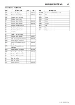
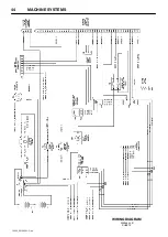
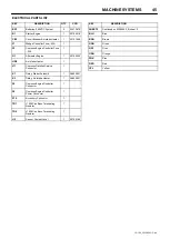
23129232 Chassis Main Harness
23376312 Control Panel Wiring Harness
The schematic diagrams show the connections for these harnesses.
The electrical circuits are protected using ATC style fuses. A fuse
should only be replaced with one of the same rating. Replacing a
fuse with one of a large rating could lead to harness damage. If a
fault occurs and the circuit does not have the appropriate size fuse,
wires could be burned in the harness and damage other circuits.


