background image

22

OPERATING INSTRUCTIONS

7/124 - 10/104, 10/124 - 14/114, 14/84


LANGUAGES AND UNITS

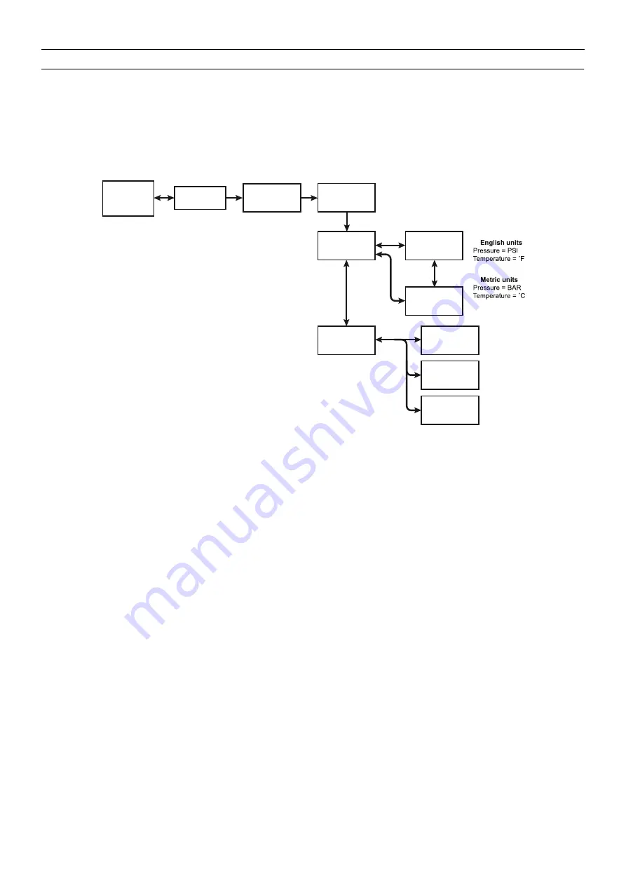
The MidPort is user configured to display in English, Spanish, or French languages and in either English or Metric units. The Language and Display
units can be changed by accessing the Setup Menu. To access the Setup Menu, press and hold the ENTER Button while the Default Screen of
Engine Hours is displayed until the Main Menu appears. Scroll to the Setup option using the DOWN Button then press the ENTER Button. Use the
DOWN or UP Buttons to highlight the chosen unit and PRESS the ENTER Button to select. To return to the Default Screen of Engine Hours, use
the DOWN Button to highlight the Main Screen menu item and press the ENTER Button. 

See Figure 5.

Figure 5

M Setup
-> Display
Units

M Units
-> English
Metric

M Units
English
-> Metric

M Language
-> English
Spanish

M Language
English
-> Spanish

-> French
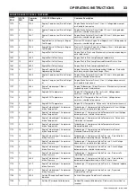
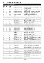
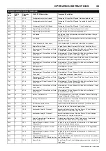
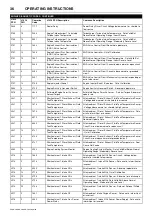
Return
Main Screen

M Setup
Display
-> Units

Press & Hold 

Enter Button

-> languages
Machine
Return

M Main Menu
Service
-> Setup

Default
Screen

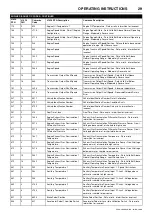
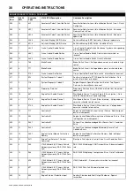
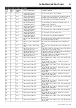
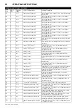
Summary of Contents for 10/104

Page 1: ...portant safety information and must be made available to personnel who operate and maintain this machine 46692958_en_C_04 18 7 124 10 104 10 124 14 114 14 84 OPERATION MAINTENANCE MANUAL Original Instruction SERIAL No 660200 ...

Page 2: ......

Page 3: ...y Directive 13 2000 14 EC The Noise Emission Directive 14 2014 68 EU The Pressure Equipment Directive 15 2014 29 EU The Simple Pressure Vessels Directive 16 97 68 EC The emission of engines for no road mobile machinery 31 2014 35 EU The Low Voltage Equipment Directive 17 and their amendments 18 Conformity with the Noise Emission Directive 2000 14 EC 19 20 22 Type kW 22 Type kW 7 20 17 5 96LWA 97LW...

Page 4: ......

Page 5: ...que settings table Compressor lubrication 81 MACHINE SYSTEMS 89 FAULT FINDING 92 OPTIONS 102 PARTS ORDERING ABBREVIATIONS SYMBOLS Contact the company for serial number Up to Serial No From Serial No Not illustrated Option WDG Generator option AR As required HA High ambient machine S R G Site running gear H R G High speed running gear bg Bulgarian cs Czech da Danish de German el Greek en English es...

Page 6: ...in the approved parts list may create hazardous conditions over which the company has no control Therefore the company cannot be held responsible for equipment in which non approved repair parts are installed The company reserves the right to make changes and improvements to products without notice and without incurring any obligation to make such changes or add such improvements to products sold ...

Page 7: ...sure control WARNING Corrosion risk WARNING Air gas flow or Air discharge WARNING Pressurised vessel WARNING Hot and harmful exhaust gas WARNING Flammable liquid WARNING Maintain correct tyre pressure Refer to the GENERAL INFORMATION section of this manual WARNING Before connecting the tow bar or commencing to tow consult the Operation Maintenance manual WARNING For operating temperature below 0 C...

Page 8: ...s machine Do not remove the Operating and Maintenance manual and manual holder from this machine Do not stack Do not operate the machine without the guard being fitted Do not stand on any service valve or other parts of the pressure system Do not operate with the doors or enclosure open Do not use fork lift truck from this side Do not exceed the trailer speed limit No naked lights Do not open the ...

Page 9: ...dbrake and wheel chocks Compressor oil filling Diesel fuel No open flame Parking brake Rough Service Designation Wet Location Operation Engine oil sump drain Separator tank drain Engine coolant drain Engine oil drain Compressor coolant drain Fuel tank drain Operational status of the engine emission filter Engine emissions system temperature may be high Disable active regeneration of the engine emi...

Page 10: ...rogress Engine oil Fuel level point Pressure control Malfunction Battery charging condition Low pressure High pressure Engine malfunction High compressor temperature Compressor malfunction Low engine oil pressure High engine temperature WARNING Daily drain of rainwater Check correct angle of tilt Ultra low sulphur diesel fuel only 15ppm sulphur maximum Low DEF and fuel warning beacon DEF drain ...

Page 11: ...ISO SYMBOLS 7 7 124 10 104 10 124 14 114 14 84 Replace any cracked protective shield ...

Page 12: ... WILL RESULT Never operate unit with guards covers or screens removed Keep hands hair clothing tools blow gun tips etc well away from moving parts Compressed air Compressed air can be dangerous if incorrectly handled Before doing any work on the unit ensure that all pressure is vented from the system and that the machine cannot be started accidentally Ensure that the machine is operating at the ra...

Page 13: ... provided at the socket control panel in the event of electrical hazards associated with generator operation Use this second control to immediately isolate all electrical power to all sockets then use the key control to stop the engine Operation of the generator must be in accordance with recognised electrical codes and local health and safety codes The generator set should be operated by those wh...

Page 14: ...the vehicle towing hitch and on variable height running gear adjustment of the drawbar To ensure full braking efficiency the front towing eye section must always be set level When adjusting variable height running gear Ensure front towing eye section is set level When raising towing eye set rear joint first then front joint When lowering towing eye set front joint first then rear joint After setti...

Page 15: ...GENERAL INFORMATION 11 7 124 10 104 10 124 14 114 14 84 Fixed Height Running Gear Braked Variable Height Running Gear Braked ...

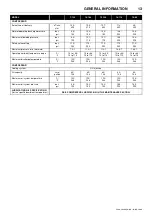
Page 16: ...1370 1830 1374 1692 1975 350 2130 Variable Height Braked 4443 MIN 4220 MAX 1798 2541 2424 405 MIN 930 MAX 2791 MIN 3014MAX 1375 435 460 1370 1830 1374 1692 1975 350 2130 LRG Less Running Gear plus skids 2685 1563 1634 2765 2424 1720 343 1380 1374 1537 1468 1539 2760 2780 2020 ALL DIMENSIONS IN MLLIMETRES Dimensions marked with are subject to a 10mm tolerance Dimensions marked with are subject to a...

Page 17: ...e ratio absolute 7 9 1 11 3 1 11 3 1 14 8 1 14 8 1 Operating ambient temperature range C F 10 to 46 14 to 115 10 to 46 14 to 115 10 to 46 14 to 115 10 to 46 14 to 115 10 to 46 14 to 115 Maximum discharge temperature C F 120 248 120 248 120 248 120 248 120 248 COMPRESSOR Cooling system Oil Injection Oil capacity Litre gallon 40 10 6 40 10 6 40 10 6 40 10 6 40 10 6 Maximum oil system temperature C F...

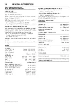
Page 18: ...ull load 7 124 10 104 2200 1950 revs min 1 RPM 10 124 14 144 2350 2100 revs min 1 RPM 14 84 2100 revs min 1 RPM Speed at idle 1500 revs min 1 RPM Electrical system 24V negative earth Power available at 2200 revs min 1 7 124 10 104 14 84 QSB4 5 130 HP 97 kW 130 HP Power available at 2500 revs min 1 10 124 14 144 QSB4 5 163 HP 122 kW 163 HP Fuel tank capacity 238 litres 63 US GAL Oil specification R...

Page 19: ...sions to walls floors etc Adequate clearance needs to be allowed around and above the machine to permit safe access for specified maintenance tasks Ensure that the machine is positioned securely and on a stable foundation Any risk of movement should be removed by suitable means especially to avoid strain on any rigid discharge piping Attach the battery cables to the battery s ensuring that they ar...

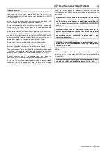
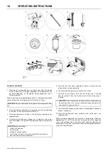
Page 20: ...ned 6 Check the radiator coolant level with the unit level 7 Open the service valve s to ensure that all pressure is relieved from the system Close the service valve s when all pressure is relieved 9 Check that the emergency stop switch is not engaged Pull knob to release if necessary 10 Close the manual relief valve inside the unit on the top of the separator tank When starting or operating the m...

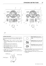
Page 21: ... Button Used to start and shutdown the compressor control system and gauge panel 6 KeyPad Used to start shutdown and operate the compressor 7 Exhaust System Cleaning Switch Provides operator control of the Exhaust Cleaning System 8 Custom Pressure Switch Used to activate the custom pressure mode This feature is not available on all machines 9 Emergency Stop Switch Used to stop the machine in the e...

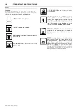
Page 22: ...ne item unit at a time Pressing and holding the UP Button continuously scrolls up through parameter lists menu choices or increases a value until the end of the parameter list menu choices or maximum parameter value is reached DOWN The DOWN Button functions identical to the UP Button with the exception that its direction for all displays menu choices and values is down or decreasing ENTER Pressing...

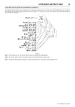
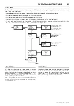
Page 23: ...inuously loops through the Quick View Screens i e when the last screen is reached pressing the DOWN Button displays the first screen and vice versa Figure 6 Note 1 Only the parameters that are available from the engine or compressor will be displayed Note 2 Unit times out after 3 minutes of inactivity and returns to the Default Screen of Engine Hours Note 3 Pressing the Enter Button while viewing ...

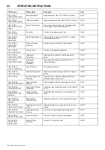
Page 24: ...occurrence amount of times this failure has occurred Displayed in case of a compressor related fault CPR Code one two or three digit number identifying the component or system fault Figure 1 When present an ALERT with the number of alert conditions will popup on the screen the user will press the UP or DOWN Button to display the alert or press the ENTER Button to acknowledge an alert has occurred ...

Page 25: ... service intervals can be changed by pressing the ENTER Button while on the default screen that displays the engine hours Using the UP or DOWN Buttons to highlight the desired interval and press the ENTER Button to select Use the UP and DOWN Buttons to increase or decrease the number of hours Hours will decrement with every hour on the engine Use the DOWN Button to highlight the Main Screen menu i...

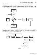
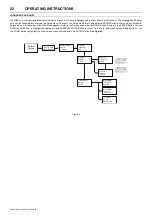
Page 26: ... Menu appears Scroll to the Setup option using the DOWN Button then press the ENTER Button Use the DOWN or UP Buttons to highlight the chosen unit and PRESS the ENTER Button to select To return to the Default Screen of Engine Hours use the DOWN Button to highlight the Main Screen menu item and press the ENTER Button See Figure 5 Figure 5 M Setup Display Units M Units English Metric M Units English...

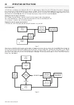
Page 27: ...n the compressor engine is not running If the Control Panel is powered ON and the engine has not run for 3 minutes above 45 F 7 C or 15 minutes at or below 45 F 7 C the control system will automatically power OFF Power can be restored by pressing the Main Power Button In the event of a fault this feature is not active and the power will remain on until the fault has been acknowledged or the contro...

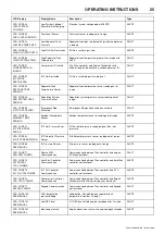
Page 28: ... Engine Shutdown FAULT CPR CODE 18 LOW OIL PRESSURE Low Oil Pressure Low engine oil pressure FAULT CPR CODE 19 HIGH FUEL TEMP High Fuel Temperature Engine fuel temperature greater than 180 F Engine derate ALERT CPR CODE 28 Incorrect Engine ECU Calibration Engine ECU has a different calibration that what is expected Engine will not crank ALERT CPR CODE 29 ENGINE SHUTDOWN Engine Shutdown Unknown Eng...

Page 29: ...LT CPR CODE 58 AMBIENT TEMP SENSOR Ambient Temperature Sensor Ambient temperature sensor reading out of range ALERT CPR CODE 61 IQ FILTER PRES ERROR IQ Filter Pressure Error IQ filter outlet pressure reading higher than inlet pressure ALERT CPR CODE 63 IQ DIFF PRES SENSOR IQ Differential Pressure Sensor IQ differential pressure sensor reading out of range ALERT CPR CODE 64 SEE MANUAL IQ Pressure S...

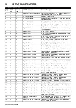
Page 30: ...d but above normal operational range Most Severe Level 101 3 1843 Engine Crankcase Pressure Crankcase Pressure Circuit Voltage above normal or shorted to high source 101 4 1844 Engine Crankcase Pressure Crankcase Pressure Circuit Voltage below normal or shorted to low source 101 2 1942 Engine Crankcase Pressure Crankcase Pressure Data erratic intermittent or incorrect 101 15 1974 Engine Crankcase ...

Page 31: ...2 Engine Coolant Pressure Coolant Pressure Sensor Circuit Voltage below normal or shorted to low source 109 18 233 Engine Coolant Pressure Coolant Pressure Data Valid But Below Normal Operating Range Moderately Severe Level 110 3 144 Engine Coolant Temperature Engine Coolant Temperature 1 Sensor Circuit Voltage above normal or shorted to high source 110 4 145 Engine Coolant Temperature Engine Cool...

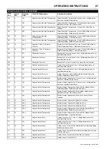
Page 32: ...a Valid But Above Normal Operating Range Least Severe Level 168 18 441 Battery Potential Power Input 1 Battery 1 Voltage Data Valid But Below Normal Operating Range Moderately Severe Level 168 16 442 Battery Potential Power Input 1 Battery 1 Voltage Data Valid But Above Normal Operating Range Moderately Severe Level 168 17 3724 Battery Potential Power Input 1 Battery 1 Voltage Data Valid But Below...

Page 33: ...ck Data erratic intermittent or incorrect 411 2 1866 Engine Exhaust Gas Recirculation 1 Differential Pressure Exhaust Gas Recirculation Differential Pressure Data erratic intermittent or incorrect 411 3 2273 Engine Exhaust Gas Recirculation 1 Differential Pressure Exhaust Gas Recirculation Differential Pressure Sensor Circuit Voltage above normal or shorted to high source 411 4 2274 Engine Exhaust...

Page 34: ...prietary Data link Proprietary Data link Error OEM Vehicle Data link Abnormal update rate 626 18 487 Engine Start Enable Device 1 Start Enable Device 1 Canister Empty Ether Injection Data Valid But Below Normal Operating Range 626 3 2738 Engine Start Enable Device 1 Start Enable Device 1 Circuit Ether Injection Voltage above normal or shorted to high source 626 4 2739 Engine Start Enable Device 1 ...

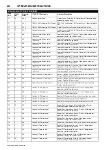
Page 35: ...t Back Pressure Regulator Control Circuit Voltage Below Normal or Shorted to Low Source 649 5 5273 Engine Exhaust Back Pressure Regulator Control Circuit Engine Exhaust Back Pressure Regulator Control Circuit Current Below Normal or Open Circuit 651 5 322 Engine Injector Cylinder 01 Injector Solenoid Driver Cylinder 1 Circuit Current below normal or open circuit 651 7 1139 Engine Injector Cylinder...

Page 36: ...ut 2 Circuit Voltage above normal or shorted to high source 702 5 4724 Auxiliary I O 02 Auxiliary Input Output 2 Circuit Current below normal or open circuit 702 6 4725 Auxiliary I O 02 Auxiliary Input Output 2 Circuit Current above normal or grounded circuit 703 3 529 Auxiliary I O 03 Auxiliary Input Output 3 Circuit Voltage above normal or shorted to high source 723 7 731 Engine Speed 2 Engine S...

Page 37: ...ne ECU Temperature Sensor Circuit Voltage below normal or shorted to low source 1136 2 699 Engine ECU Temperature Engine ECU Temperature Data erratic intermittent or incorrect 1172 3 691 Engine Turbocharger 1 Compressor Intake Temperature Turbocharger 1 Compressor Intake Temperature Circuit Voltage above normal or shorted to high source 1172 4 692 Engine Turbocharger 1 Compressor Intake Temperatur...

Page 38: ...Engine Misfire Cylinder 6 Engine Misfire Cylinder 6 Condition Exists 1347 4 271 Engine Fuel Pump Pressurizing Assembly 1 Engine Fuel Pump Pressurizing Assembly 1 Circuit Voltage below normal or shorted to low source 1347 3 272 Engine Fuel Pump Pressurizing Assembly 2 Engine Fuel Pump Pressurizing Assembly 1 Circuit Voltage above normal or shorted to high source 1347 7 281 Engine Fuel Pump Pressuri...

Page 39: ...pen circuit 1761 13 4732 Aftertreatment 1 Diesel Exhaust Fluid Tank Temperature Aftertreatment 1 Diesel Exhaust Fluid Tank Level Sensor Out of Calibration 1761 6 4738 Aftertreatment 1Diesel Exhaust Fluid Tank Level Aftertreatment 1 Diesel Exhaust Fluid Tank Level Sensor Circuit Current above normal or grounded circuit 1761 11 4739 Aftertreatment 1 Diesel Exhaust Fluid Tank Level Aftertreatment 1 D...

Page 40: ...haust Fluid Tank Temperature Sensor Voltage above normal or shorted to high source 3031 2 1679 Aftertreatment 1 Diesel Exhaust Fluid Tank Temperature Aftertreatment 1 Diesel Exhaust Fluid Tank Temperature Data erratic intermittent or incorrect 3031 9 4572 Aftertreatment 1 Diesel Exhaust Fluid Tank Temperature Aftertreatment 1 Diesel Exhaust Fluid Tank Temperature Abnormal Update Rate 3031 5 4682 A...

Page 41: ...43 Aftertreatment 1 Exhaust Gas Temperature 2 Aftertreatment Exhaust Gas Temperature 2 Data Valid But Below Normal Operating Range Moderately Severe Level 3251 3 1879 Aftertreatment 1 Diesel Particulate Filter Differential Pressure Aftertreatment Diesel Particulate Filter Differential Pressure Sensor Circuit Voltage above normal 3251 4 1881 Aftertreatment 1 Diesel Particulate Filter Differential P...

Page 42: ...el Exhaust Fluid Quality Sensor Circuit Voltage above normal or shorted to high source 3364 13 1714 Aftertreatment 1 Diesel Exhaust Fluid Tank 1 Quality Aftertreatment Diesel Exhaust Fluid Quality Out of Calibration 3364 11 1715 Aftertreatment 1 Diesel Exhaust Fluid Tank 1 Quality Aftertreatment Diesel Exhaust Fluid Quality Root Cause Not Known 3364 1 3866 Aftertreatment 1 Diesel Exhaust Fluid Tan...

Page 43: ...ly 1 Circuit Voltage below normal or shorted to low source 3509 3 386 Sensor supply voltage 1 Sensor Supply 1 Circuit Voltage above normal or shorted to high source 3510 4 187 Sensor supply voltage 2 Sensor Supply 2 Circuit Voltage below normal or shorted to low source 3510 3 227 Sensor supply voltage 2 Sensor Supply 2 Circuit Voltage above normal or shorted to high source 3511 4 238 Sensor supply...

Page 44: ...3 Aftertreatment Diesel Particulate Filter Outlet Pressure Aftertreatment 1 Diesel Particulate Filter Outlet Pressure Sensor Circuit Voltage above normal or shorted to high source 3610 4 3134 Aftertreatment Diesel Particulate Filter Outlet Pressure Aftertreatment 1 Diesel Particulate Filter Outlet Pressure Sensor Circuit Voltage below normal or shorted to low source 3610 2 3135 Aftertreatment Dies...

Page 45: ...perating Range Mo 4334 3 3571 Aftertreatment 1 Diesel Exhaust Fluid Doser Absolute Pressure Aftertreatment 1 Diesel Exhaust Fluid Pressure Sensor Voltage above normal or shorted to high source 4334 4 3572 Aftertreatment 1 Diesel Exhaust Fluid Doser Absolute Pressure Aftertreatment 1 Diesel Exhaust Fluid Pressure Sensor Voltage below normal or shorted to low source 4334 18 3574 Aftertreatment 1 Die...

Page 46: ...t 1 SCR Catalyst Outlet Gas Temperature Aftertreatment 1 SCR Outlet Temperature Sensor Circuit Voltage below normal or shorted to low source 4363 2 3148 Aftertreatment 1 SCR Catalyst Outlet Gas Temperature Aftertreatment 1 SCR Outlet Temperature Sensor Data erratic intermittent or incorrect 4363 0 3165 Aftertreatment 1 SCR Catalyst Outlet Gas Temperature Aftertreatment 1 SCR Outlet Temperature Dat...

Page 47: ... Temperature Sensor Circuit Voltage below normal 4809 2 3154 Aftertreatment Warm Up Diesel Oxidation Catalyst Intake Temperature Aftertreatment Warm Up Diesel Oxidation Catalyst Intake Temperature Data erratic intermittent or incorrect 4809 13 3166 Aftertreatment Warm Up Diesel Oxidation Catalyst Intake Temperature Aftertreatment Warm Up Diesel Oxidation Catalyst Intake Temperature Sensor Swapped ...

Page 48: ...ormal or open circuit 5394 7 3568 Aftertreatment Diesel Exhaust Fluid Dosing Valve Aftertreatment Diesel Exhaust Fluid Dosing Valve Mechanical system not responding or out of adjustment 5394 2 3755 Aftertreatment Diesel Exhaust Fluid Dosing Valve Aftertreatment Diesel Exhaust Fluid Dosing Valve Data erratic intermittent or incorrect 5395 16 3337 Engine Idle Fuel Quantity Engine Idle Fuel Quantity ...

Page 49: ...ttent or incorrect 5742 9 4151 Aftertreatment Diesel Particulate Filter Temperature Sensor Module Aftertreatment Diesel Particulate Filter Temperature Sensor Module Abnormal update rate 5742 12 4158 Aftertreatment Diesel Particulate Filter Temperature Sensor Module Aftertreatment Diesel Particulate Filter Temperature Sensor Module Bad intelligent device or component 5742 3 4161 Aftertreatment Dies...

Page 50: ...sel Oxidation Catalyst Temperature Sensor Module Aftertreatment Warm Up Diesel Oxidation Catalyst Temperature Sensor Module Data Valid But Above Normal Operating Range Moderately Severe Level 5797 11 4258 Aftertreatment Warm Up Diesel Oxidation Catalyst Temperature Sensor Module Aftertreatment Warm Up Diesel Oxidation Catalyst Temperature Sensor Module Root Cause Not Known 5798 2 4245 Aftertreatme...

Page 51: ...rted to high source 520199 4 194 Cruise Control Cruise Control Resistive Signal Circuit Voltage below normal or shorted to low source 520320 7 2699 Crankcase Depression Valve Crankcase Depression Valve Mechanical system not responding or out of adjustment 520332 3 2755 Cruise Control Cruise Control Resistive 2 Signal Circuit Voltage above normal or shorted to high source 520332 4 2756 Cruise Contr...

Page 52: ...ssive Time Since Last Engine Air Shutoff Maintenance Test Excessive Time Since Last Engine Air Shutoff Maintenance Test Condition Exists 524286 31 5617 Aftertreatment 1 Diesel Oxidation Catalyst System Aftertreatment 1 Diesel Oxidation Catalyst System Special Instruction 524286 31 9491 Reserved for temporary use Condition Exists 524286 31 9999 Reserved for temporary use Condition Exists ...

Page 53: ...tion always set the 3 way valve to the OFF position before starting As soon as machine goes to load the valve can be set to required position ON OFF for the reheater 3 When the Wait To Start message on the MidPort changes to Total Engine Hours press and release Green Start Button 4 Engine will crank until engine starts or engine starting time limit is reached The first Green light on the Start But...

Page 54: ...e M Orifice N Manual blowdown valve Dual mode models 7 124 10 104 and 10 124 14 114 are capable of operating at two pressure modes 1 The Low Pressure Mode is activated by pressing the Low Pressure Button In this mode the compressor will regulate according to the air demand between 0 and 12 m3 min at 6 9 bar regulated set pressure for the 7 124 10 104 or between 0 and 12 7 m3 min at 10 3 bar regula...

Page 55: ...e navigated using the UP DOWN and ENTER Buttons 5 If the Main Power Button is not pressed within 3 minutes if ambient temperature is above 45 F 7 C or 15 minutes if ambient temperature is 45 F 7 C or below of the keypad use the compressor will automatically shut off If the battery needs to be disconnected wait at least 70 seconds after stopping the engine CAUTION Failure to allow turbocharger cool...

Page 56: ...ows customer set required pressure independently on HI LO mode The main reason for implementation is to reduce fuel consumption as much as possible by setting the exact pressure value required The machine is equipped with an additional pressure regulator and solenoid valve Custom pressure activation controls outlet pressure and engine speed Settings described for 7 124 10 110 unit Set Custom press...

Page 57: ... metal catalyst packaged in a stainless steel container The honeycomb structure with many small parallel channels presents a high catalytic contact area to exhaust gasses As the hot gases contact the catalyst several exhaust pollutants are converted into harmless substances carbon dioxide and water The diesel oxidation catalyst is designed to oxidize carbon monoxide gas phase hydrocarbons and the ...

Page 58: ...ong as the engine The DEF system requires maintenance of the filter situated in the Bosch dosing pump at the required intervals see scheduled maintenance Using any fluid other then the proper DEF fluid will contaminate and render the dosing system inoperable causing the engine to stop Should any contamination occur then the tank needs to be removed and cleaned before filling with the correct DEF f...

Page 59: ...te information or rendered unusable by drilling cutting etc Do not allow lubricants or coolants to be released into land surfaces or drains Do not dispose of a complete machine without documentation relating to instructions for its use LONG TERM STORAGE RECOMMENDATIONS 6 months or more Spare Airends Long term storage of airends should include filling the airend with the standard compressor fluid P...

Page 60: ...arrier base unless it is a Portable Power provided system NOTE The maintenance schedule in this manual describes the service intervals that should be followed for normal applications of this compressor This page may be reproduced and used as a checklist by service personnel In more severe applications such as but not limited to sandblasting quarry drilling well drilling and oil and gas drilling mo...

Page 61: ...mining the optimum intervals for your application MAINTENANCE Daily Weekly Monthly 6 months or 500 hrs 1 year or 1000 hrs 2000 hrs 4500 hrs 5000 hrs Compressor Oil Level C Engine Oil Level C Coolant Level C Gauges Lamps C Air Cleaner Service Indicators C Air Cleaner Dust Ejector Valve C Aftertreatment Exhaust Piping C Fuel Tank C Refill Fuel Water Separator D Fluid Leaks C Radiator Filler Cap C Di...

Page 62: ...mperatures high dust concentration high humidity as well as using lower grade oils and fuels will require a decrease in maintenance intervals Contact your Doosan Infracore Portable Power dealer for more information or assistance in determining the optimum intervals for your application Daily Weekly Monthly 6 months or 500 hrs 1 year or 1000 hrs 2000 hrs 4500 hrs 5000 hrs Wheels Bearings Seals etc ...

Page 63: ...als are valid for near perfect conditions only High ambient temperatures high dust concentration high humidity as well as using lower grade oils and fuels will require a decrease in maintenance intervals Contact your Doosan Infracore Portable Power dealer for more information or assistance in determining the optimum intervals for your application MAINTENANCE Initial 500 miles 850 km Daily Weekly M...

Page 64: ... opening or removing panels or covers to work inside a machine ensure that anyone entering the machine is aware of the reduced level of protection and the additional hazards including hot surfaces and intermittently moving parts the machine cannot be started accidentally or otherwise by posting warning signs and or fitting appropriate anti start devices Prior to attempting any maintenance work on ...

Page 65: ...ng and remove the filter element by releasing the nut If the safety element is to be renewed thoroughly clean the interior of the filter housing prior to removing the safety element Inspection Check for cracks holes or any other damage to the element by holding it up to a light source or by passing a lamp inside Check the seal at the end of the element and replace if any sign of damage is evident ...

Page 66: ...RGE COOLER PIPEWORK Inspect all hoses and clips on the charge cooler pipe work Engine damage will occur if the charge cooling system leaks HOSES All components of the engine cooling air intake system should be checked periodically to keep the engine at peak efficiency At the recommended intervals see the SERVICE MAINTENANCE CHART inspect all of the intake lines to the air filter and all flexible h...

Page 67: ...ing gear to the frame should be checked periodically for tightness refer to the SERVICE MAINTENANCE CHART for frequency and re tightened where necessary Refer to the TORQUE SETTING TABLE later in this section RUNNING GEAR WHEEL BEARINGS Wheel bearings should be packed with heavy duty wheel bearing grease every 6 months Wheel bearings should be greased per the Maintenance Schedule in this manual Th...

Page 68: ...le and re insert the cable 5 adjusting it to give a small amount of play Remove the M10 safety screw from the handbrake pivot All Models Engage the handbrake lever 1 and check that the position of the equaliser plate 10 is at right angles to the pulling direction If necessary correct the position of the equaliser plate 10 on the cables 11 The compression spring 9 must only be slightly pre tensione...

Page 69: ...ust if necessary Important Check the brake actuators and cables 11 The brake actuators must not be pre tensioned Excessive operation of the handbrake lever which may have been caused by worn brake linings must not be corrected by re adjusting shortening the brake linkage 7 Re adjustment The handbrake lever 1 should be engaged forcefully several times to set the braking system Check the setting of ...

Page 70: ... the drawbar may NOT be connected to the towing vehicle After connecting the coupling to the towing vehicle turning the handle IS FORBIDDEN Lifting of the trailer by turning the handle IS STRICTLY FORBIDDEN 1 Warning label 2 Lock spring 3 Upward adjustment 4 Downward adjustment Service interval Lubricate in accordance with regulation SK70003 Before the first journey After the first loaded journey ...

Page 71: ...may now be removed If the bellows 36 is damaged it must be replaced Assembly Before mounting all the new and removed parts have to be lubricated in accordance with regulation SK70003 Attach the shaft of the coupling head 1 onto the drawtube 45 and adjust until the holes overlap Insert both bolts 2 Screw on new fixing nuts 3 and fasten them with a torque wrench Bolt M12 to 77 5Nm Bolt M14 to 125 5N...

Page 72: ... shock absorber 33 Push the shock absorber 33 into the drawtube 45 from the front and bolt together with the shock absorber bracket 35 Fasten the hexagonal nut 31 with a tightening moment of 30 5Nm Push the unit 46 from the front into the housing place the disc 37 if present between the housing and the shock absorber bracket 35 and fasten with lock bolts 40 41 At the same time mount the hand grip ...

Page 73: ...asten it with a tightening moment of 30 2Nm Screw the hexagonal nut 22 and the clevis 23 onto the cable and adjust it in accordance with regulation SK70008 Put the pin 26 through the balance lever 76 and the clevis 23 and lock it with the disc 25 and the SL clip 24 Insert the cable into the slot in the spindle top part See View B and mount it with the transmission lever 17 Mount the transmission l...

Page 74: ...single axle so that the handbrake lever can be moved down Undo the SL clips 63 and pull out the pin 62 Replace the damaged spring pack Assembly Mount the new spring pack onto the spring pack bracket 60 and secure it with the SL clip 63 Mount the spring pack 61 with the handbrake lever insert the pin 62 and secure with the SL clip 63 Set up the whole braking system according to general KNOTT regula...

Page 75: ...ed high performance grease N3 Using a brush apply a thin even layer of SPHEEROL EPL2 or equivalent NLGI 2 Grade lubricant Part to be lubricated a Grease nipple b Bush c Piston rod d Hole e Top middle part f Bottom middle part g Holes for handbrake h Drawbar coupling i Conversion lever coupling j Tube k Pin l Adjustment bolt welded m Gearing n Top spindle o Thread p Bottom spindle q Adjustment nut ...

Page 76: ...2 based high performance grease N3 Using a brush apply a thin even layer of SPHEEROL EPL2 or equivalent NLGI 2 Grade lubricant Part to be lubricated a Grease nipple b Bush c Piston rod d Hole e Top middle part f Bottom middle part g Holes for handbrake h Drawbar coupling i Conversion lever coupling j Tube k Pin l Adjustment bolt welded m Gearing n Top spindle o Thread p Bottom spindle q Adjustment...

Page 77: ...R then adjust the gap in detail B to 0 5mm 6 If gap e is greater than 28mm in detail R then adjust the gap in detail B to 0 5mm Coupling cross section showing position of detail A Detail A a Fixing nut M10 8 DIN980 ATTENTION Do NOT lock fixing nuts M10 8 DIN980 b Hexagonal head nut M16x1 5 DIN936 Torque 30Nm 2Nm Cross section showing positions of details B C and R c Hexagonal head nut M16x1 5 DIN9...

Page 78: ... the plastic cap upwards to unlock and turn counter clockwise until tension is relieved Proceed to turn the cap clockwise one full turn 2 If high pressure regulation needs adjustment repeat Step 2 at High Pressure Regulator 3 Close Service Valves After Starting Unit 4 Push the Service Air Button on the Control Panel The unit should speed up and then unload and drop back to IDLE With the unit unloa...

Page 79: ...TTERN TYPICAL CIRCULAR TORQUE PATTERN CAPSCREW OR NUT THREAD SIZE AND PITCH NOMINAL DESIGN TORQUE 8AE J249 GRADE 5 HEAD MARKING 8AE J249 GRADE 8 HEAD MARKING Nm FT LBF Nm FT LBF 1 4 20 11 8 16 12 5 16 18 24 17 33 25 3 8 16 42 31 59 44 7 16 14 67 49 95 70 1 2 13 102 75 144 106 9 16 12 148 109 208 154 5 8 11 203 150 287 212 3 4 10 361 266 509 376 ...

Page 80: ... M8 X 1 25 26 19 36 27 43 31 M10 X 1 5 52 38 72 53 84 62 M12 X 1 75 91 67 126 93 147 109 M14 X 2 145 107 200 148 234 173 M16 X 2 226 166 313 231 365 270 M20 X 2 5 441 325 610 450 713 526 TABLE 3 WHEEL TORQUE CHART Wheel Torque Chart Inch Wheel Torque Chart Metric 1 2 lug nuts Torque Ft Lbs Torque N m Torque ft Lbs 13 Wheel 80 90 15 Wheel 105 115 M12 Bolts 85 95 62 70 16 Wheel 105 115 M14 Bolts 145...

Page 81: ...s in storage an earlier change may be necessary as oil deteriorates with time as well as by operating conditions An oil change is good insurance against the accumulation of dirt sludge or oxidised oil products Completely drain the separator tank piping and cooler If the oil is drained immediately after the compressor has been run for some time most of the sediment will be in suspension and therefo...

Page 82: ...eatment damage Please read the engine manual for more details Design operating pressure Ambient temperature Compressor oil specification 7 bar to 14 bar 100 psi to 200 psi 23 C to 52 C 10 F to 125 F Preferred PRO TEC Alternate ISO Viscosity Grade 46 with rust and oxidisation inhibitors designed for air compressor service 14 bar and above 200 psi and above 23 C to 52 C 10 F to 125 F Preferred XHP 6...

Page 83: ...MAINTENANCE 79 7 124 10 104 10 124 14 114 14 84 ...

Page 84: ...80 MAINTENANCE 7 124 10 104 10 124 14 114 14 84 ...

Page 85: ...MACHINE SYSTEMS 81 7 124 10 104 10 124 14 114 14 84 Compressor and Engine Harness Wiring Diagram 46680011 Rev A sheet 1 of 8 ...

Page 86: ...82 MACHINE SYSTEMS 7 124 10 104 10 124 14 114 14 84 Compressor and Engine Harness Wiring Diagram 46680011 Rev A sheet 2 of 8 ...

Page 87: ...MACHINE SYSTEMS 83 7 124 10 104 10 124 14 114 14 84 Compressor and Engine Harness Wiring Diagram 46680011 Rev A sheet 3 of 8 ...

Page 88: ...84 MACHINE SYSTEMS 7 124 10 104 10 124 14 114 14 84 Compressor and Engine Harness Wiring Diagram 46680011 Rev A sheet 4 of 8 ...

Page 89: ...MACHINE SYSTEMS 85 7 124 10 104 10 124 14 114 14 84 Compressor and Engine Harness Wiring Diagram 46680011 Rev A sheet 5 of 8 ...

Page 90: ...86 MACHINE SYSTEMS 7 124 10 104 10 124 14 114 14 84 Compressor and Engine Harness Wiring Diagram 46680011 Rev A sheet 6 of 8 ...

Page 91: ...MACHINE SYSTEMS 87 7 124 10 104 10 124 14 114 14 84 Control Panel Harness Wiring Diagram 46680009 Rev A sheet 2 of 3 ...

Page 92: ...88 MACHINE SYSTEMS 7 124 10 104 10 124 14 114 14 84 ...

Page 93: ... won t start or run Battery disconnect switch off Check switch position and operation Check switch position and operation Emergency stop pushed Check emergency stop switch position and operation Low battery voltage Check battery condition recharge if necessary Check electrolyte level add if necessary Check cable connections clean and tighten as needed Blown fuse Identify and replace fuse See Elect...

Page 94: ...ighten or replace belt set Loose wire connection Check wires at switches and connectors to find loose connection Make repairs See Electronic Service Manual Low battery voltage Check battery condition recharge if necessary Check electrolyte level add if necessary Check cable connections clean and tighten as needed Malfunctioning alternator Repair or replace alternator 6 High compressor oil temperat...

Page 95: ...g conditions Move compressor to cleaner environment Wrong air filter element s Install correct air filter element s Inadequate air filter element cleaning Install new air filter element s Incorrect stopping procedure Comply with procedure in this manual 11 Compressor will not unload Malfunctioning inlet unloader butterfly valve Inspect valve Make adjustments per this manual Malfunctioning pressure...

Page 96: ...ecting the condensate and the added cost of disposing of the condensate which is often regulated by local regulations Ensure that the compressed air temperature always remains above freezing temperatures typically 7 C 45 F at any ambient temperature down to 23 C 20 F This prevents the need for heat tracing systems or any manual adjustment to prevent freezing of the compressed air system All drain ...

Page 97: ... is bypassed Standard Operation selected the delivered air pressure will be approximately equal to the separator tank pressure If the IQ System operation is selected the delivered air pressure will be slightly less depending on the restriction of the filters MAINTENANCE Daily Maintenance Verify during full load maximum compressed air delivery operation the IQ System filter restriction is not exces...

Page 98: ...94 OPTIONS 7 124 10 104 10 124 14 114 14 84 PRIMARY AND SECONDARY FILTER MAINTENANCE FIGURE 1 FIGURE 2 FIGURE 3 FIGURE 4 FIGURE 5 ...

Page 99: ...OPTIONS 95 7 124 10 104 10 124 14 114 14 84 WATER SEPARATOR MAINTENANCE FIGURE 1 FIGURE 2 FIGURE 3 FIGURE 4 FIGURE 5 FIGURE 6 ...

Page 100: ...wer levels causing overheating reduced engine life and reduced airend life CAUTION Excessively restricted filter elements may cause an increase in the amount of aerosol water and oil carryover which could result in damage to downstream equipment Normal service intervals should not be exceeded CAUTION Blockage of the condensate will result in flooding of the vessels If flooding occurs excessive con...

Page 101: ...g condensate in the aftercooler to drain This is to prevent cooler damage at freezing temperatures These drains are plugged through the compressor frame and will expel condensation to atmosphere Should site contamination by this condensate be prohibited the user can connect an additional section of drain hose and route into an allowed drain point MAINTENANCE Daily Maintenance Verify during full lo...

Page 102: ...wise to take the shutdown above high idle speed by a suitable margin When using this setting procedure it may be found that the engine occasionally shuts down during the normal operation If so turn the adjuster clockwise by a further one half turn 7 Ensure the adjuster locknut is fully tightened Use a thread lock adhesive on the locknut threads MAINTENANCE Three monthly 1 Disconnect intake pipewor...

Page 103: ...tor oil level and fill as necessary PRIOR TO STARTING Check the lubricator oil level and replenish as necessary MAINTENANCE Check the lubricator oil level and replenish as necessary FAULT FINDING OPTION LUBRICATOR WARNING Ensure that the lubricator filler cap is re tightened correctly after replenishing with oil WARNING Do not replenish the lubricator oil or service the lubricator without first ma...

Page 104: ...s or significant areas of damage i e dents of more than a few millimetres in depth Three Monthly Remove spark arrestor Tap with a soft mallet to loosen any internal deposits and shake out Also by shaking check for any loose internal baffles Six Monthly or 1500 hours operation whichever is sooner Examine the exhaust discharge in darkness whilst repeatedly loading and accelerating the engine If any ...

Page 105: ...d at the same time reduces the standard idling speed to the minimum possible level that the compressor permits If the air starts to be drawn and the service air pressure drops below 35 of the maximum pressure recorded during standard idling the machine enters the normal operating mode Engine speed increases to rated engine speed and the compressor starts supplying the maximum amount of air ECO Mod...

Page 106: ... production HOW TO USE PARTS LIST a Turn to Parts List b Locate the area or system of the compressor in which the desired part is used and find illustration page number c Locate the desired part on the illustration by visual identification and make note of part number and description HOW TO ORDER The satisfactory ordering of parts by a purchaser is greatly dependent upon the proper use of all avai...

Page 107: ...arranty negligence indemnity strict liability or otherwise shall not exceed the purchase price of the part upon which such liability is based The Company shall in no event be liable to the Purchaser any successors in interest or any beneficiary of this order for any consequential incidental indirect special or punitive damages arising out of this order or any breach thereof or any defect in or fai...

Page 108: ......

Page 109: ......

Page 110: ...Doosan Bobcat EMEA s r o U Kodetky 1810 263 12 Dobříš Czech Republic www doosanportablepower eu ...

Reviews: